


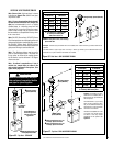
15
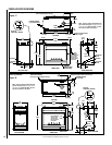
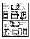
NOTE: DIAGRAMS & ILLUSTRATIONS ARE NOT TO SCALE.
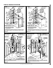
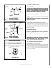
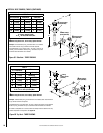
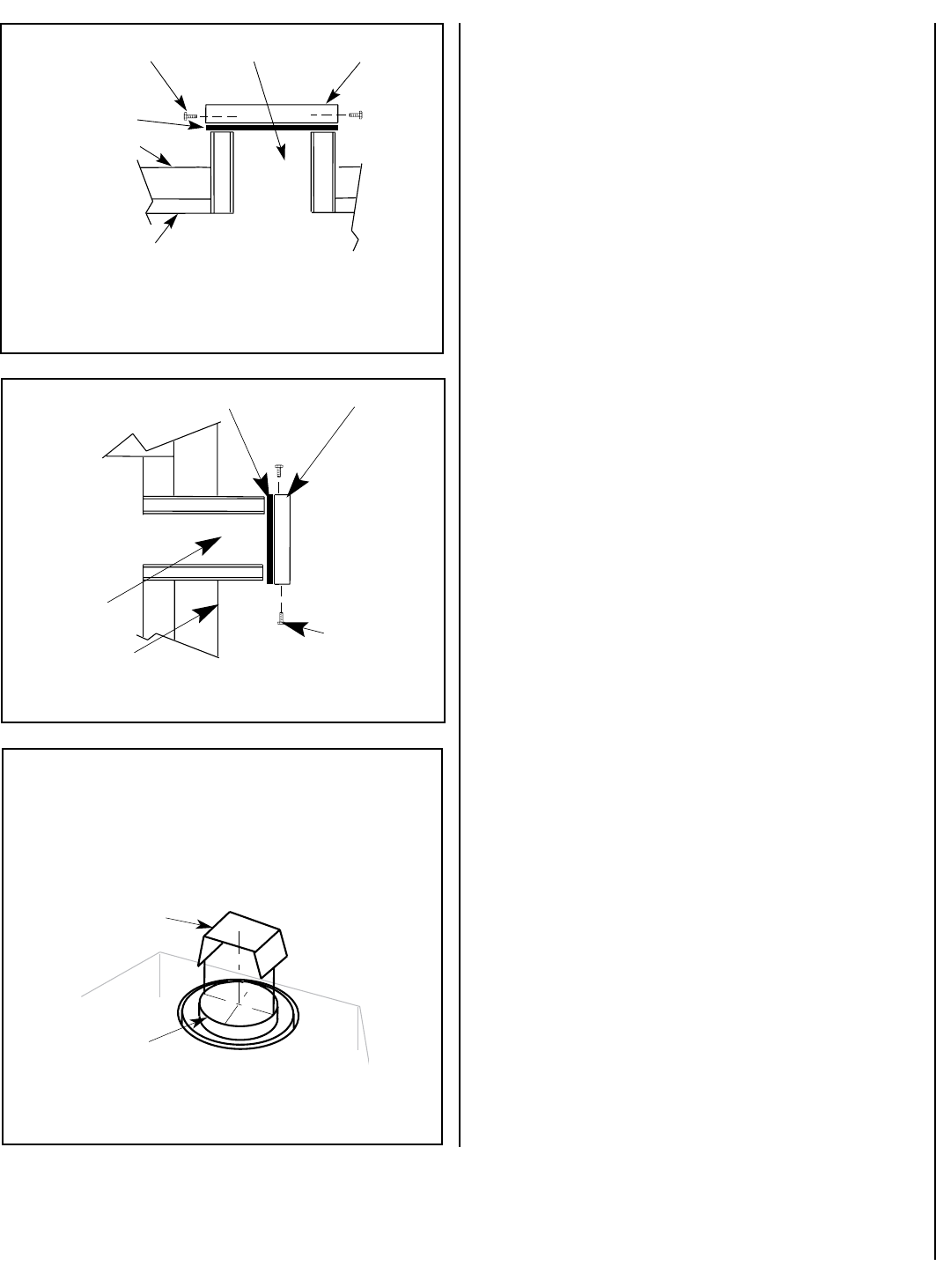
Securing Screws
(OUTSIDE of
Appli
ance)
Insulation
Top Vent
Vent Seal Cap
Firebox Top
Cabinet Top
CROSS SECTION
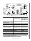
SIDE VENT SEAL CAP REMOVAL
(SIDE VENT INSTALLATIONS ONLY)
Insulation
Vent Seal Cap
Securing Screws
Side Vent
Cabinet Back
CROSS SECTION
(INSIDE of Appli
ance)
(OUTSIDE of
Appli
ance)
(INSIDE of
Appli
ance)
Figure 22 -
Figure 23 -
TOP VENT SEAL CAP REMOVAL
(TOP VENT INSTALLATIONS ONLY)
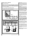
Step 4. INSTALL THE VENT SYSTEM
General Information
These instructions should be used as a guideline and do not supersede
local codes in any way. Install venting according to local codes, these
instructions, the current National Fuel Gas Code (ANSI-Z223.1) in the
USA or the current standards of CAN/CSA-B149.1 in Canada.
Ensure clearances are in accordance with local installation codes and
the requirements of the gas supplier.
Dégagement conforme aux codes d'installation locaux et aux exigences
du foumisseunde gaz.
Use only approved venting components. See Approved Vent
Components on Page 2.
These fireplaces must be vented directly to the outside.
The vent system may not service multiple appliances, and must never
be connected to a flue serving a solid fuel burning appliance. The vent
pipe is tested to be run inside an enclosed wall (such as a chase). There
is no requirement for inspection openings in the enclosing wall at any of
the joints in the vent pipe.
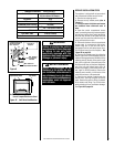
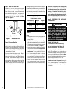
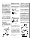
Installation of Vent Restrictor
A vent restrictor may be needed with this appliance. The restrictor is
installed in the appliance top flue outlet as shown in Figure 24, either
before adding vent, from above, or after installation of vent from below,
within the firebox. The restrictor is self securing through a positive
friction fit.
Determine the venting for the appliance. If the vent run will include at
least 8 feet of vertical rise, then install the restrictor in the appliance
collar before connecting any vent (Refer to Figure 24 ). Place the
restrictor inside the appliance vent collar and press in place.
Note: The restrictor is included within the firebox.
Select Venting System - Horizontal or Vertical
With the appliance secured in framing, determine vent routing and identify
the exterior termination location. The following sections describe vertical
(roof) and horizontal (exterior wall) vent applications. Refer to the section
relating to your installation. A list of approved venting components are
shown on Pages 38 and 39.
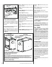
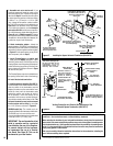
Figure 24
Appliance
Vent Outlet
Restrictor
Inner
Fireplace
Collar
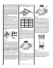
VENT RESTRICTOR INSTALLATION
A vent restrictor may be needed when vertically terminating the vent
system above the roof (when using the appliance top vent), install a vent
restrictor in the top vent of the fireplace outlet.
If needed, install the restrictor as shown, either from inside or outside the
unit, in the inner fireplace collar.
Top Shown - Rear Similar