


30
NOTE: DIAGRAMS & ILLUSTRATIONS ARE NOT TO SCALE.
When first lighting the appliance, it will take a
few minutes for the line to purge itself of air.
Once purging is complete, the pilot and burner
will light and operate as indicated in the instruc-
tion manual.
Subsequent lighting of the appliance will not
require such purging. Inspect the pilot flame (re-
move logs, if necessary, handling carefully).
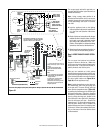
Millivolt Appliance Checkout
The pilot flame should be steady, not lifting
or floating. Flame should be blue in color with
traces of orange at the outer edge.
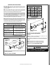
The top 3/8" (10 mm) at the pilot generator
(thermopile) and the top 1/8" minimum (tip)
of the quick drop out thermocouple should be
engulfed in the pilot flame.
The flame should project 1" (25 mm) beyond the
hood at all three ports (see Figure 57). Replace
logs if removed for pilot inspection.
To light the burner; turn “ON” the remote wall
switch and rotate the gas valve control knob
counterclockwise to the “ON” position (“ON”
will be at the top side of the valve).
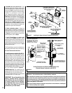
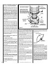
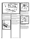
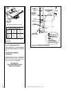
Figure 56
Piezo Ignitor
Gas Valve
Modesty Panel
Control
Compartment
Access panel
ON/OFF
Switch
Hinge Pin
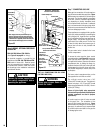
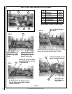
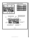
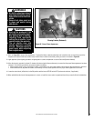
Step 9. INSTALL VERMICULITE, GLOW-
ING EMBERS AND LOGS
NOTE: Turn off all electricity to the appliance
before you install vermiculite, embers and logs.
DO NOT attempt to install the logs until the ap-
pliance installation has been completed, the gas
line connected and tested for leaks and the initial
burner operation has been checked out.
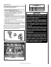
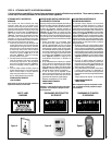
MILLIVOLT
Thermocouple
Hood Igniter Rod
3/8" Min
(9 mm)
Thermopile
Pilot
Nozzels
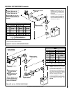
Electronic Appliance Checkout
To light the burner, turn ‘ON’ the unit mounted
On/Off switch or the optional remote wall switch.
Ensure the igniter lights the pilot. The pilot
flame should engulf the flame rod as shown
in Figure 58.
Figure 57
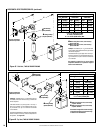
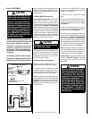
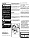
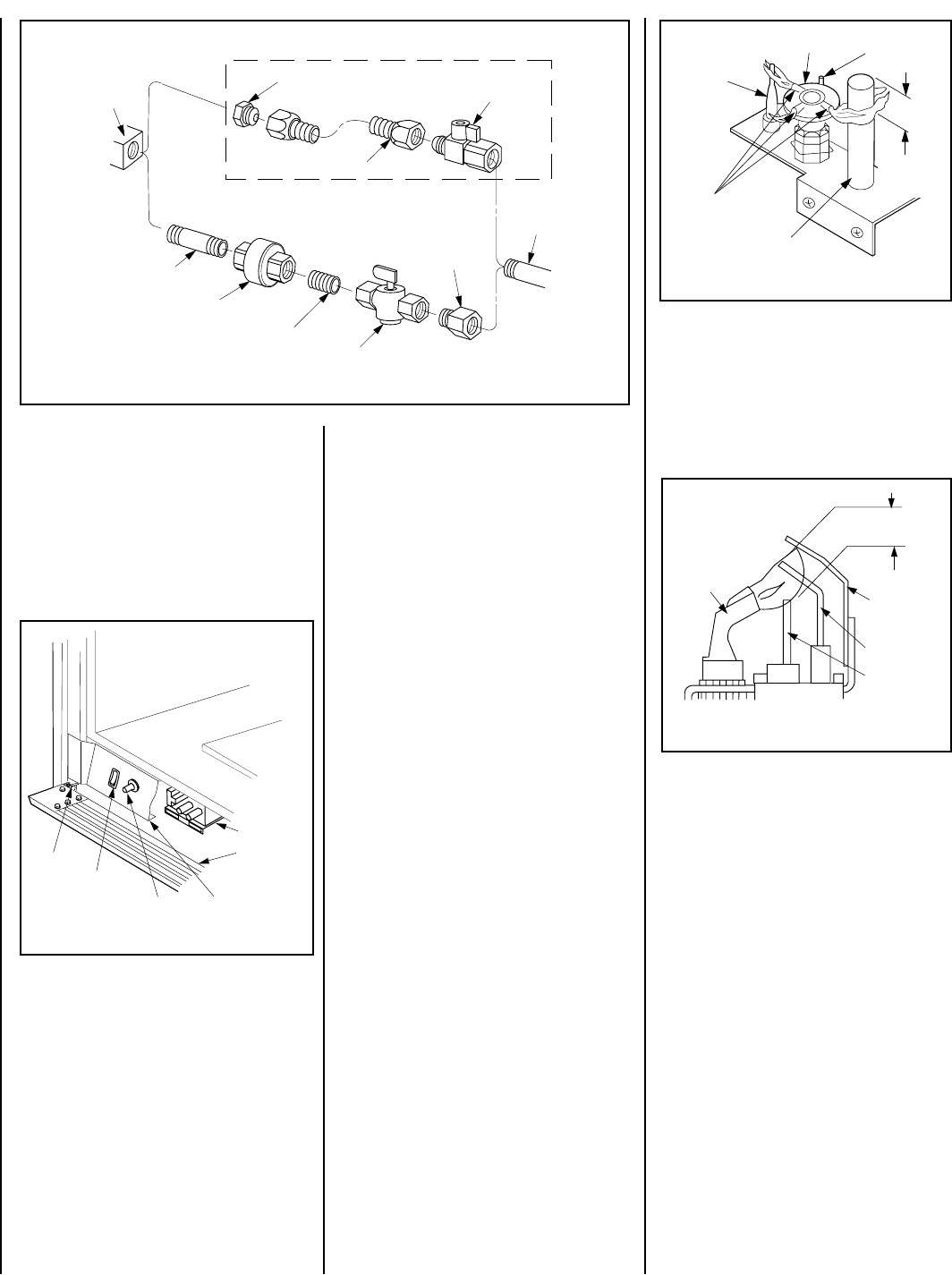
Figure 55 - GAS CONNECTION
Gas
Stub
1/2" x 3/8" Flare
Shut-Off Valve
3/8" Flex Tubing
3/8" NPT x 3/8"
Flare Fitting
3/8" Nipple
3/8" Union
3/8" Close Nipple
3/8" Shut-Off Valve
1/2" x 3/8"
Reducer
Gas
Valve
Optional Gas Flex-Line Connector
ELECTRONIC
Proper Flame
Adjustment
Pilot
Nozzle
3/8 To 1/2 Inch
(9 mm to 13 mm)
Ground
Electrode
Flame Rod
Hot Surface
Igniter
Figure 58