


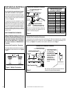
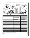
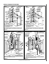
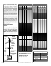
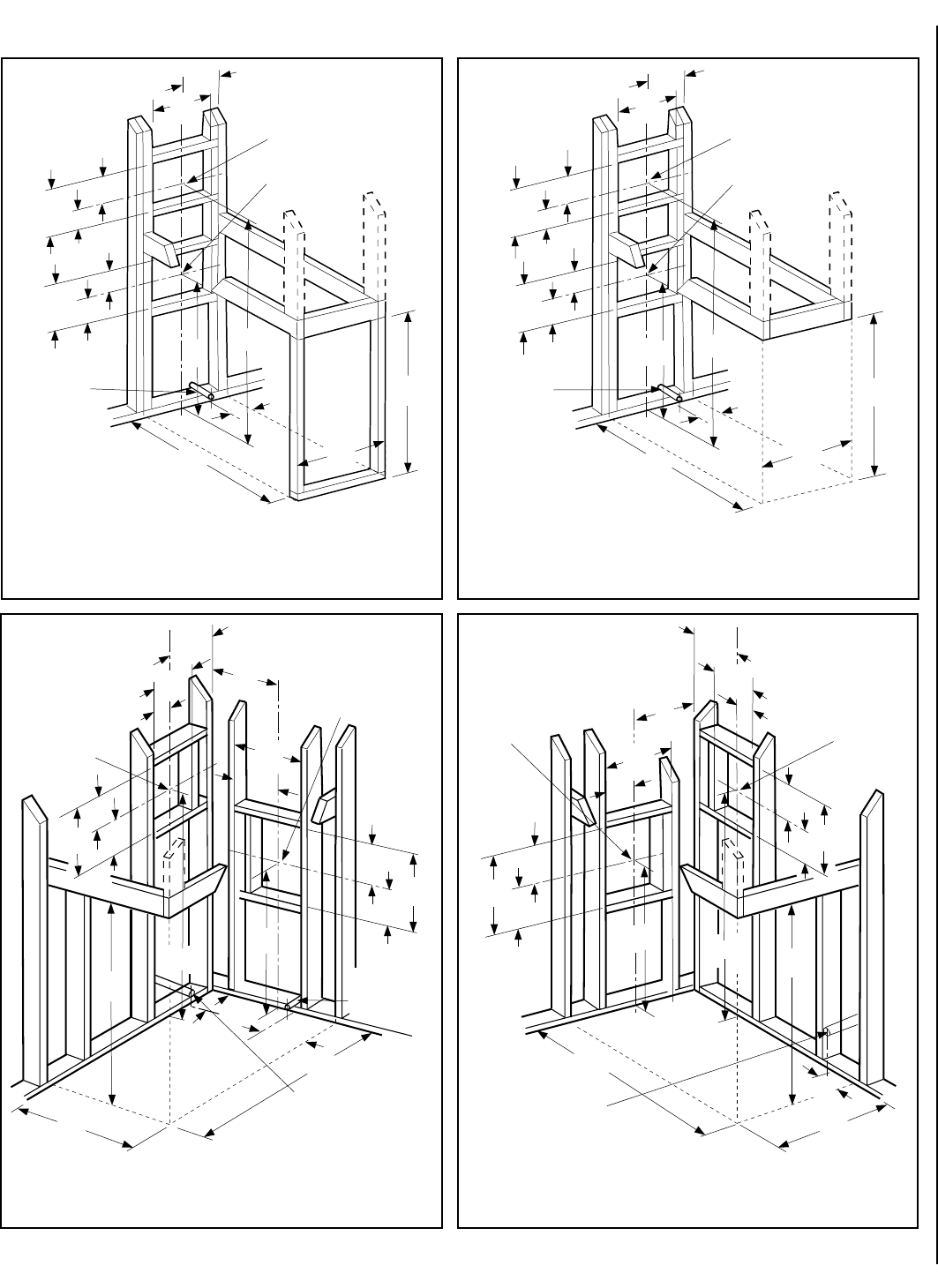
11
NOTE: DIAGRAMS & ILLUSTRATIONS ARE NOT TO SCALE.
Gas Line
Center of gas line
is 3 in. (76 mm)
up from floor.
*41-1/2
(1054)
***48-1/2
(1232)
26-3/4
(679)
11-3/8
(267)
Dimension A
Secure Vent - 47-1/8 (1197)
Secure Flex - 47-3/4 (1213)
7
(178)
5-1/8
(130)
12-1/8
(308)
10-1/2
**22-3/4
(578)
EDVST
(See-Through)
VENT FRAMING -
TOP VENT WITH
ONE 90º ELBOW
VENT FRAMING -
REAR VENT WITH
NO ELBOWS
inches (millimeters)
7
(178)
5-1/8
(130)
12-1/8
(308)
6-1/4
(159)
A
Minimum Framing
Stud Size is 2x4
*This dimension can be reduced to 41 inches (1041 mm). This results in 0 in. (0 mm)
clearance between framing and unit framing spacers. (The 41-1/2 in. dimension permits
easier fireplace installation, if unit is installed after framing is erected.)
**This dimension based on 5/8” drywall.
For 1/2” drywall use 23”.
***Provide Additional Space For Side Vent
Seal Cap If Installing Against A Solid Wall
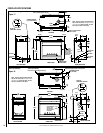
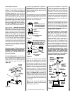
EDVPF
(Peninsula)
Gas Line
Center of gas line
is 3 in. (76 mm)
up from floor.
*41-1/2
(1054)
***43-5/8
(1108)
26-3/4
(679)
11-3/8
7
(178)
5-1/8
(130)
12-1/8
(308)
VENT FRAMING -
TOP VENT WITH
ONE 90º ELBOW
VENT FRAMING -
REAR VENT WITH
NO ELBOWS
inches (millimeters)
7
(178)
(130)
(308)
6-1/4
(159)
A
Minimum Framing
Stud Size is 2x4
(267)
(289)
**22-3/4
(578)
Dimension A
Secure Vent - 47-1/8 (1197)
Secure Flex - 47-3/4 (1213)
*This dimension can be reduced to 41 inches (1041 mm). This results in 0 in. (0 mm)
clearance between framing and unit framing spacers. (The 41-1/2 in. dimension permits
easier fireplace installation, if unit is installed after framing is erected.)
**This dimension based on 5/8” drywall.
For 1/2” drywall use 23”.
***Provide Additional Space For Side Vent
Seal Cap If Installing Against A Solid Wall
10-1/2
12-1/8
5-1/8
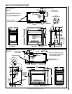
*41-1/2
(1054)
**43-5/8
(1108)
*This dimension can be reduced to 41 inches (1041 mm). This results in 0 in. (0 mm) clearance
between framing and unit framing spacers. (The 4-1/2 in. dimension permits easier fireplace
installation, if unit is installed after framing is erected.)
26-3/4
(679)
5-1/8
12-1/8
(308)
10-1/2
(
267
)
(130)
12-1/2
(318)
7
(178)
10-1/2
(
267
)
10-3/8
(
264
)
5-1/4
(133)
5-1/4
(133)
24
(610)
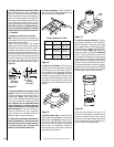
EDVCL (Corner-Left)
VENT FRAMING -
TOP VENT WITH
ONE 90º ELBOW
VENT FRAMING -
REAR VENT WITH
NO ELBOWS
inches (millimeters)
6-1/4
(159)
9-3/4
(248)
Optional Gas Line Location
Center of gas line is 3 in. (76 mm)
up from floor.
A
Gas Line
Center of gas line
is 3 in. (76 mm)
up from floor.
Minimum Framing
Stud Size is 2x4
7
(178)
5-1/8
(130)
12-1/8
(308)
Dimension A
Secure Vent - 47-1/8 (1197)
Secure Flex - 47-3/4 (1213)
**Provide Additional Space For Side Vent
Seal Cap If Installing Against A Solid Wall
*41-1/2
(1054)
24
(610)
*This dimension can be reduced to 41 inches (1041 mm). This results in 0 in. (0 mm) clearance
between framing and unit framing spacers. (The 41-1/2 in. dimension permits easier fireplace
installation, if unit is installed after framing is erected.)
26-3/4
(679)
10-1/2
(
267
)
12-1/2
(318)
7
(178)
5-1/8
(130)
12-1/8
(308)
10-1/2
(
267
)
10-3/8
(
264
)
5-1/4
(133)
5-1/4
(133)
EDVCR (Corner-Right)
VENT FRAMING -
TOP VENT WITH
ONE 90º ELBOW
VENT FRAMING -
REAR VENT WITH
NO ELBOWS
inches (millimeters)
Gas Line
Center of gas line is
3 in. (76 mm) up from floor.
9-7/8
(251)
A
Minimum Framing
Stud Size is 2x4
7
(178)
5-1/8
(130)
12-1/8
(308)
Dimension A
Secure Vent - 47-1/8 (1197)
Secure Flex - 47-3/4 (1213)
**43-5/8
(1108)
**Provide Additional Space For Side Vent
Seal Cap If Installing Against A Solid Wall
Figure 14
Figure 13
Figure 15
Figure 16
FIREPLACE FRAMING SPECIFICATIONS