


22
NOTE: DIAGRAMS & ILLUSTRATIONS ARE NOT TO SCALE.
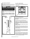
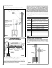
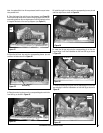
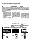
Ref. Air shutter Patent:
U.S. Pat. 5,553,603
Figure 34
Adjustment Rod Up
(1/8" Open Position)
Air Shutter
Burner T
ube
Adjusting Set Screw
Adjustment Rod Down
(full open position)
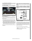
Burner Air Shutter Adjustment
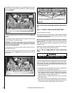
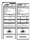
CAUTION
The cast iron stove top is very heavy and may
require a minimum of two people to lift; one person
on each side (the CI1500 series cast top weighs
~20 pounds and the CI2500 series cast top weighs
~40 pounds).
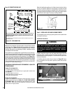
Stove Cast Iron Top
Trivet
Trivet
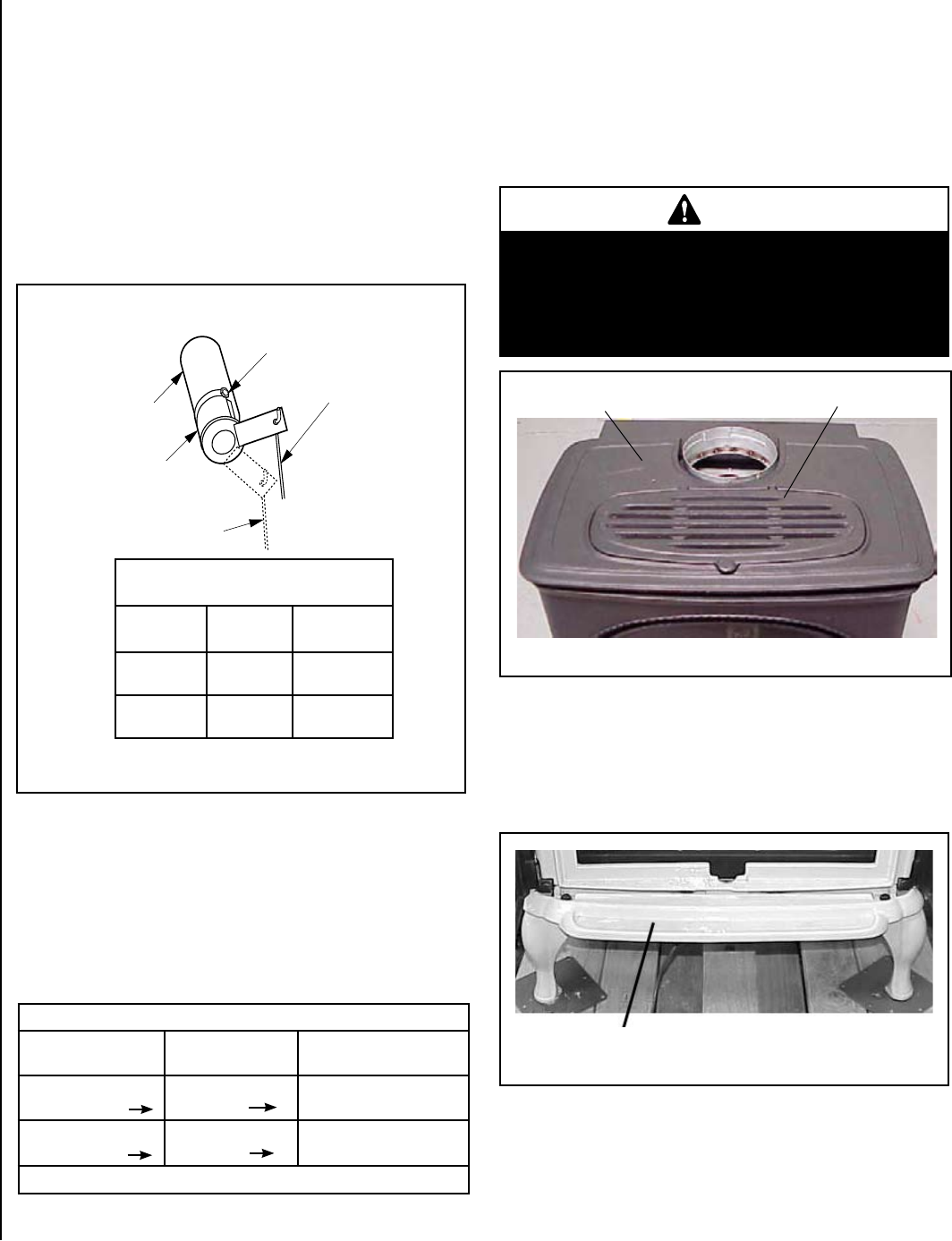
Ash Lip
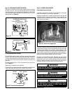
Figure 36
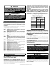
B. Locate the ash lip from packaging (Step 2). Remove the 2 bolts from
the tapped holes in the ash lip. Align the ash lip below the firebox as
shown in Figure 36 (the tapped holes in ash lip should align with
corresponding slots below firebox). Reinstall the 2 bolts that were
removed from the ash lip (finger tight only. If a tool is used, be careful
not to overtighten).
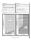
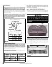
Air Shutter Adjustment Guidelines:
If the burner flame appearance differs greatly from what is shown
on Page 21 (see Figure 33), some adjustment from standard for the
air shutter gap may be necessary (to compensate for variables in the
installation and fuel such as, BTU value / composition, gas pressure,
specific gravity of gas, altitude, etc.).
The following chart is provided to aid you in achieving the correct air
shutter adjustment for your installation.
Air Shutter Adjustment Guidelines:
Amount of
Primary Air
Flame Color Air Shutter
Adjustment
If air shutter is
closed too far
Flame will
be yellow
Air shutter gap should be
increased
If air shutter is open
too far
Flame will
be blue
Air shutter gap should be
decreased
Table 9
When satisfied that the appliance operates properly, proceed to finish
the installation. Leave the control knob in the ON position and the
on/off switch in the OFF position.
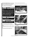
Step 16. INSTALL STOVE TOP, TRIVET AND ASH LIP
A. Place the cast iron top into position on the stove top (See Figure 35).
Place the trivet into the recess on the cast iron top (See Figure 35).
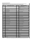
Main Burner Factory Air Shutter
Opening Setting - Inches (millimeter)
Model Natural
Gas
Propane
Gas
CI1500DVF
5/16"
(7.93 mm)
5/8"
(15.9 mm)
CI2500DVF
1/2"
(12.7 mm)
5/8"
(15.9 mm)
Burner Adjustment
Initially, always position the air shutter to the factory setting as shown
in Figure 34 (adjustment rod is located in the lower control area). This
can be done by moving the adjustment rod up or down accordingly.
Allow the burner to operate for at least 15 minutes. Observe the flame
continuously. If it appears weak or sooty as previously described,
adjust the air shutter to a more open position until the desired flame
appearance is achieved.
The adjustment rod and associated adjustable air shutter is patented
technology. Flame adjustments can be made quickly and accurately to
taste without the need of disassembling the appliance and waiting for
30 minutes after each adjustment.
Figure 35