


21
NOTE: DIAGRAMS & ILLUSTRATIONS ARE NOT TO SCALE.
IMPORTANT
Ensure that the front glass panel is in place and
sealed during adjustment.
WARNING
Air shutter adjustment should only be performed by
a qualified professional service technician.
CAUTION
The adjustment rod and nearby appliance surfaces
are hot. Exercise caution to avoid injury while
adjusting flame appearance.
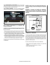
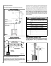
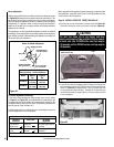
Figure 31
Burner
On/Off
Switch
Top View
Front
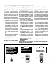
SIT Millivolt Gas Valve Controls
H
I
L
O
W
TPTH TP TH
P
I
L
O
T
P
I
L
O
T
O
N
it
O
F
F
HI / LO Knob
Variable Flame Height Adjustment
Manifold Pressure Port
Inlet
Pressure
Port
Main Gas
Control Knob
Piezo Igniter
IN
OUT
Piezo Igniter
Figure 30
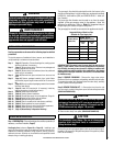
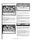
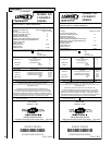
Step 14. CHECKING APPLIANCE OPERATION
With gas line installed run initial system checkout before closing up
the front of the unit. Follow the pilot lighting instructions provided
in the Homeowner's Care and Operation Instructions (or pull out the
instruction label located in a holder on rear shield of stove) . For piezo
igniter location see Figure 30.
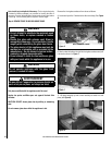
Sooting is indicated by black puffs developing at the tips of very long
orange flames. Sooting results in black deposits forming on the logs,
appliance inside surfaces and on exterior surfaces adjacent to the
vent termination. Sooting is caused by incomplete combustion in the
flames and lack of combustion air entering the air shutter opening. To
achieve a warm yellow to orange flame that does not soot, the shutter
opening must be adjusted between these two extremes.
No smoke or soot should be present. Reposition the logs if flames
impinge on any of them. If the logs are properly positioned and soot-
ing conditions exist, the air shutter opening on the main burner tube
should be adjusted. Normally, the more offsets in the vent system,
the greater the need for the air shutter to be opened further.
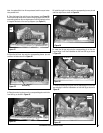
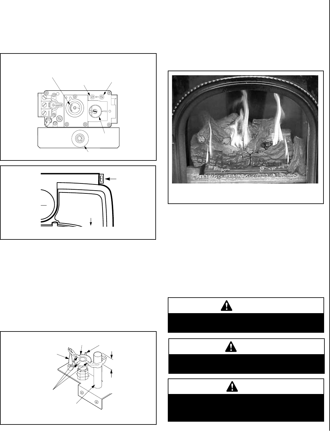
Step 15. BURNER ADJUSTMENTS
Flame Appearance and Sooting
Proper flame appearance is a matter of taste. Generally, most people
prefer the warm glow of a yellow to orange flame.
Appliances operated with air shutter openings that are too large will
exhibit flames that are blue and transparent. These weak, blue and
transparent flames are termed anemic. If the air shutter opening is too
small sooting may develop.
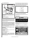
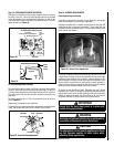
MILLIVOLT
Thermocouple
Hood Igniter Rod
3/8" Min.
(9 mm)
Thermopile
Pilot
Nozzels
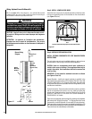
Figure 32 - Proper Pilot Flame Appearance
Figure 33 - Burner Flame Appearance
SIT Millivolt Appliance Checkout
The pilot flame should be steady, not lifting or floating. Flame should
be blue in color with traces of orange at the outer edge. The top 3/8"
(10 mm) at the pilot generator (thermopile) and the top 1/8" minimum
(tip) of the quick drop out thermocouple should be engulfed in the
pilot flame.
The flame should project 1" (25 mm) beyond the hood at all three
ports (Figure 32).
Replace logs if removed for pilot inspection.
To light the burner, rotate the gas valve control knob counterclockwise
to the “ON” position then turn “ON” the ON/OFF rocker switch.