


11
NOTE: DIAGRAMS & ILLUSTRATIONS ARE NOT TO SCALE.
Remove the screws and support plate which secure the stove legs to
the pallet. Lift stove off of the pallet and place it into position (where
unit is to be installed).
IMPORTANT NOTE: If propane is used, be aware that if the tank size is too
small (i.e. under 100-lbs, if this is the only gas appliance in the dwelling.
Ref. NPFA 58), there may be loss of pressure, resulting in insufficient fuel
delivery (which can result in sooting or other malfunctions). Any damage
resulting from an improper installation, such as this, is not covered under
the limited warranty.
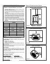
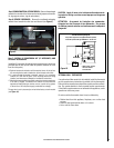
Step 2: REMOVE PACKAGING - Remove the large outer carton.
Remove all the inner packages and packing materials and set aside.
To remove the ember strip package below the stove body, carefully
cut the 2 plastic ties using scissors.
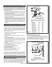
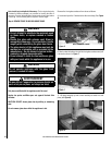
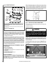
Step 3: REMOVE FROM PALLET - A. Remove the trivet, then the cast
iron stove top by carefully lifting them up and off and setting them aside
(READ CAUTION BELOW).
CAUTION
The cast iron stove top is very heavy and may require a
minimum of two people to lift; one person on each side
(the CI1500 series cast top weighs ~20 pounds and the
CI2500 series cast top weighs ~40 pounds).
CAUTION
The stove body is very heavy. The use of a heavy duty
escalara (stair step hand truck) is recommended for
lifting the stove body.
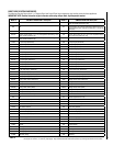
See the page numbers references in the following steps for detailed
procedures.
The typical sequence of installation follows, however, each installation is
unique resulting in variations to those described.
Step 1. (Page 11) Preparation - Plan and install gas line, venting system
and floor protection (if necessary).
Step 2. (Page 11) Remove outer carton. Remove inner packages and
packing materials and set aside.
Step 3. (Page 11) Remove stove from pallet and place into positioned
where unit is to be installed.
Step 4. (Page 12) Remove front glass enclosure from stove and set
aside.
Step 5. (Page 13) Remove packaged materials from inside firebox
and set aside (log set, bag of embers and NG to LP conversion
kit).
Step 6. (Page 13) Remove cardboard packaging material from beneath
relief door and discard.
Step 7. (Page 13) Install LP Conversion kit (if necessary). Install any
optional accessories (excluding firescreens).
Step 8. (Page 14) Install lower access door.
Step 9.
(Page 14) Venting System Installation.
Step 10. (Page 18) Connect gas supply line to the appliance. Purge Air.
Step 11. (Page 18) Install log set, ember strip and embers.
Step 12. (Page 20) Reinstall front glass enclosure.
Step 13. (Page 20) Test all connections for leaks (factory and field).
Step 14. (Page 21) Check appliance for proper operation.
Step 15. (Page 21) Adjust burner to ensure proper flame appearance.
Step 16. (Page 22) Install stove top, trivet and ash lip.
Step 17. (Page 23) Attach Safety in Operation Warnings.
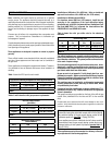
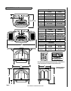
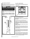
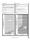
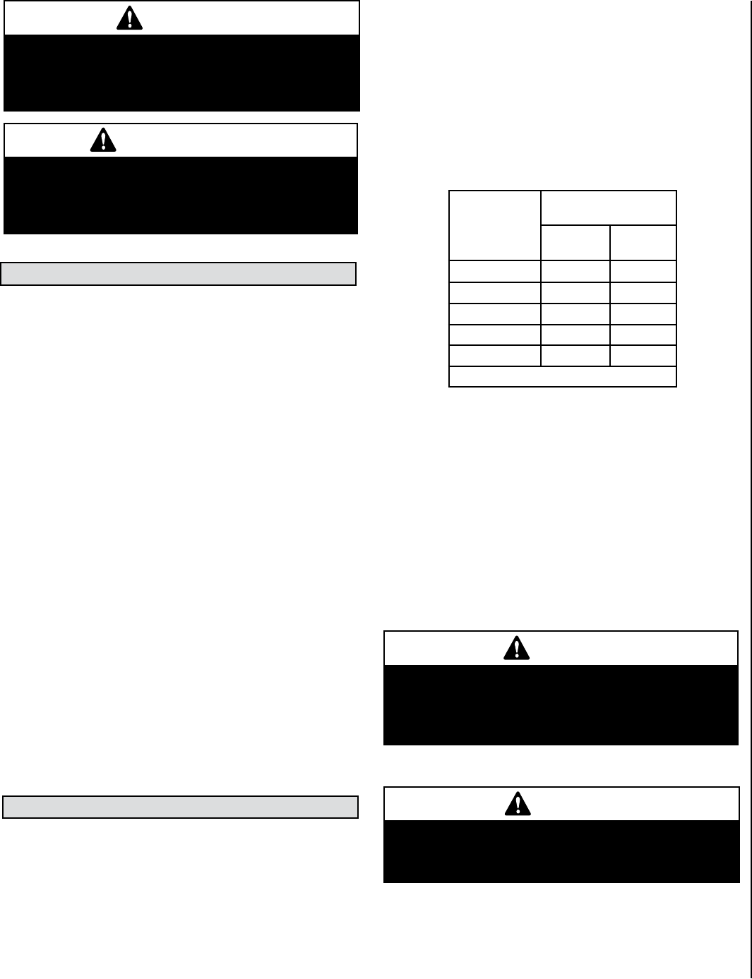
Suggested Sizing of Black Iron Pipe
Schedule 40 - Pipe Supply Line
Schedule 40 Pipe
Length (Feet)
Schedule 40 Pipe
Inside Diameter (Inches)
Natural
Gas
Propane
Gas
0-10 1/2 3/8
10-40 1/2 1/2
40-100 1/2 1/2
100-150 3/4 1/2
150-200 3/4 1/2
Table 6
B. Remove stove body from pallet (READ CAUTION BELOW).
TYPICAL INSTALLATION SEQUENCE
DETAILED INSTALLATION STEPS
Step 1: PREPARATION - Plan and install gas line and floor protection (if
necessary - see Floor Protection, Page 8).
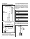
Gas Supply Line (reference Figure 18 on Page 18) - Installing a gas
supply line from the fuel supply to the appliance involves numerous con-
siderations of materials, protection, sizing, locations, controls, pressure,
sediment, and more. Certainly no one unfamiliar and unqualified should
attempt sizing or installing gas piping.
The gas supply line should be plumbed from the fuel source to the
area where the appliance is to be installed per requirements outlined
in NFPA 54 - latest edition (USA) and CAN/CSA-B149.1 - latest edi-
tion (Canada).
The proper gas line diameter must be used to run from the supply
regulator (at the gas company meter) to the appliance. Never use
galvanized or plastic pipe. Refer to Table 6 for suggested sizing of
the gas supply line if black iron pipe is being used.
The gas supply line should be connected to the appliance at step 10.
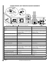
WARNING
Failure to position the parts in accordance with these
diagrams or failure to use only parts specifically
approved with this appliance may result in property
damage or personal injury.
AVERTISSEMENT
Risque de dommages ou de blessures si les pièces
ne sont pas installées conformément à ces schémas
et ou si des pièces autres que celles spécifiquement
approuvées avec cet appareil sont utilisées.