


18
NOTE: DIAGRAMS & ILLUSTRATIONS ARE NOT TO SCALE.
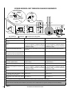
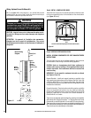
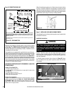
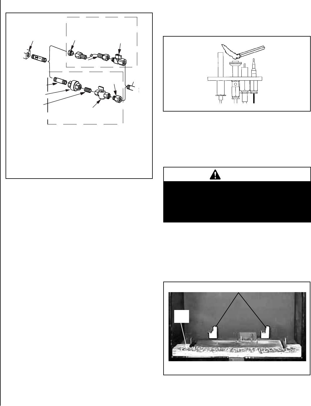
Gas
Valve
3/8" NPT x
Flare Fitting
3/8" Flex Tubing
3/8" Nipple
3/8" Union
3/8" Close
Nipple
3/8" Shut-off Valve
1/2" x 3/8"
Reducer
Gas
Stub
1/2" x 3/8" Flare
Shut-off Valve
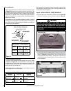
Gas Solid Line Connector
Gas Flex Line Connector
*Sediment
Trap
3"
Min
Note: The gas supply line must be installed in accordance with building codes by
a qualified installer approved and/or licensed as required by the locality. In the
Commonwealth of Massachusetts, installation must be performed by a licensed
plumber or gas fitter.
*A Sediment Trap is recommended to prevent moisture and debris in gas line from
damaging the valve.
Make gas line connections. All codes require a shut-off valve mounted
in the supply line. Figure 18 illustrates two methods for connecting
the gas supply. The flex-line method is acceptable in the U.S., however,
Canadian requirements vary depending on locality. Installation must be
in compliance with local codes.
These appliances are equipped with a gas flex line for use (where per-
mitted) in connecting the unit to the gas line. A gas flex line is provided
to aid in attaching the direct-vent appliance to the gas supply. The gas
flex line can only be used where local codes permit. See Figure 18 for
flex line description. The flex line is rated for both natural and propane
gas. A manual shut off valve is also provided with the flex line. The gas
control valve is located in the lower control compartment. To access the
valve, open the lower access door. The millivolt control valve has a 3/8"
(10 mm) NPT thread inlet port fitting.
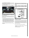
AIR PURGING PROCEDURES MUST PERFORMED BY A QUALIFIED
TECHNICIAN ONLY.
Purging Air from Supply Line
a. Turn gas supply line valve off.
b. Loosen setscrew at inlet pressure tap on upper right of control valve
(see Figure 30).
c. Turn gas supply line valve on.
d. When gas flows, turn supply valve off.
e. Close the inlet pressure tap.
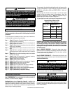
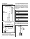
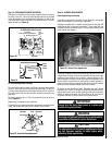
Purging Air from Appliance
Purge air from appliance by holding gas control valve down in the pilot
position until pilot will light (see Figure 19). DO NOT LIGHT A MATCH
IF YOU SMELL GAS. Light a match then allow gas flow to pilot. If the
Match “blows”, there is air in the line (purge line). If the flame is straight
and tall, there is no gas pressure.
Step 10. CONNECTING GAS LINE
Figure 18 - GAS CONNECTION
When first lighting the appliance, it will take a few minutes for the line
to purge air from the appliance. Once purging is complete, the pilot
and burner will light and operate as indicated in the instruction manual.
Subsequent lightings of the appliance will not require such purging. Inspect
the pilot flame (remove logs, if necessary, handling carefully).
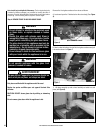
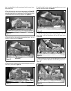
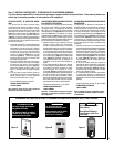
Step 11. INSTALLING LOGS AND GLOWING EMBERS
The packaged log set and bag of glowing embers are located within
the firebox of the stove.
Installation Instructions:
Figure 20
Figure 19
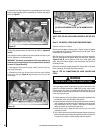
Carefully install the ember strip and seven-piece log set into the
firebox as shown in these instructions. All logs should fit onto cor-
responding pins and/or log stoppers. This will ensure a proper flame
and safe combustion.
1. Carefully place the ember strip as shown in Figure 20. Ensure
that it is pushed all the way back in position (toward the sub-floor
front flange).
WARNING
If logs are not installed according to the directions shown
here, flame impingement and improper combustion
could occur and result in soot and/or excessive produc-
tion of carbon monoxide (CO), a colorless, odorless,
toxic gas.
Ember
Strip
Rear Log Stoppers