


16
NOTE: DIAGRAMS & ILLUSTRATIONS ARE NOT TO SCALE.
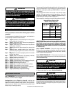
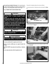
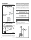
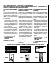
Direct-Vent Retrofit Of Existing Chimney System
An existing Class-A (wood-burning) Metal Chimney or Masonry Chim-
ney can be converted to a direct-vent system. Use one of the following
chimney conversion kits listed below. Have the existing chimney system
inspected by a professional prior to the conversion.
The chimney conversion should not be applied to the portion of the vent
system that is in the room of the appliance. Use only Co-Axial direct-
vent pipe (4” inner pipe, 6 5/8” outer pipe as listed on Page 17) from the
appliance to the retro-connector into converted flue system. Adhere to
all specifications outlined in this manual regarding clearances to combus-
tibles, vertical and horizontal vent length minimums and maximums, etc.
Read all instructions in this manual and provided by vent manufacturer
with kit carefully before starting the installation. Failure to follow the
instructions may create a fire or other safety hazard, and will void the
warranty. The following Vent System components may be safely used
with this appliance.
Figure 17
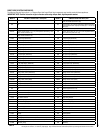
Chimney DV Liner Kits
Model Brand: SECURITY SECURE VENT / Description
SV4MCK Masonry Chimney Conversion Kit –Vertical term. Cap, cap
adapter, masonry cover, black adapter (to flex), 2 gear
clamps
SV4CCK1 Factory Built Chimney Conversion Kit – for 6” I.D., 1” insula-
tion.
SV4CCK2 Factory Built Chimney Conversion Kit – for 7” I.D., 1” insula-
tion; 8” I.D., 1” insulation; 6” I.D., 2” insulation
SV4CCK3 Factory Built Chimney Conversion Kit – for 10” I.D., 1” insula-
tion; 7” I.D., 2” insulation; 8” I.D., 2” insulation
Model Brand: SIMPSON DURA-VENT / Description
934 Masonry Chimney Conversion Kit
931 Factory Built Chimney Conversion Kit A – for 6” I.D.;
932 Factory Built Chimney Conversion Kit B – for 6”, 7” & 8”
I.D.
933 Factory Built Chimney Conversion Kit C – for 7” & 8” I.D.
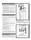
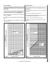
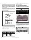
Table 7
8 feet
1 inch
minimum
Support
Brackets
Wall
Stud
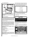
Installing Support Brackets
Install support brackets per vent manufacturers instructions.
Figure 15
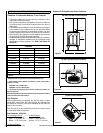
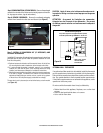
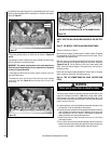
Select Venting System - Horizontal Or Vertical
The following sections describe vertical (roof) and horizontal (exterior
wall) vent applications. Refer to the section relating to your instal-
lation. A list of approved venting components is shown on Pages
16 and 17.
Vertical
Horizontal
Combustion
Air
Exhaust
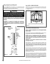
Placement:
Horizontal Runs - Requires a
support bracket every 5 feet
(152 cm).
Vertical Runs - Requires
support brackets every 8
feet (244 cm) above the
stove vent outlet..
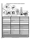
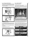
Vertical Vent Installation
Support Bracket Placement Diagram
Horizontal Vent Installation
Support Bracket Placement Diagram
Figure 16
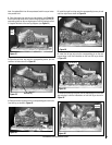
Vertical
Rise
Elbow
Horizontal / Inclined Run
(¹⁄₄" Rise per Foot of Horizontal Run in the
Direction away from the Stove)
Termination
Shown
Firestop/Spacer
Vent Sections
Support Bracket Spacing
Every 5 ft (1.52 m)
See figure for
vertical vent
Support
Brackets
Building
Support
Framing
Ceiling
Exterior
Wall
section support.