


8 EN
ABOUT DV
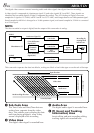
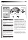
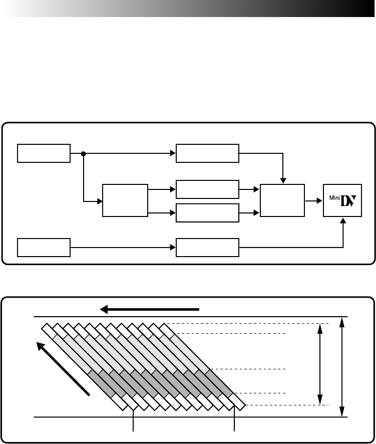
The digital video camera converts incoming audio and video signals into digital form for recording.
A video signal is composed of a luminance signal (Y) and color signals (R-Y and B-Y). These signals are
identified and recorded digitally (Digital Component Recording). The A/D (Analog to Digital) converter
samples the Y signal at 13.5 MHz, and R-Y and B-Y at 3.375 MHz, and changes them to an 8-bit quantum signal.
Sound sampled at 48 kHz is changed to a 16-bit quantum signal, and sound sampled at 32 kHz is converted
to a 12-bit signal.
NOTE:
The data recorded on a tape is digital, but the output of this camcorder is analog.
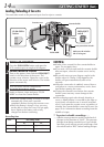
3 Audio Area
The digital audio signal is recorded here.
4 ITI (Insert and Tracking
Information) Area
Insert editing and post-recording editing
tracking signals are recorded here.
1 Sub-Code Area
The Time Code and Date/Time data are
written here, separate from the video
data. This enables you to display the date
and time during playback, even if they
weren’t displayed while recording.
2 Video Area
The digital video signal is recorded here.
10 tracks/frame
A/D
conversion
A/D
conversion
A/D
conversion
AUDIO
Color Difference
Signal (B-Y)
Recording by
rotating head
helical scan
Tape direction
Sub-Code Area
Video Area
Audio Area
ITI Area
5.24 mm / 1/5"
6.35 mm / 1/4"
This camcorder separates the data into blocks, writing one block of each data type on each track of the tape.
VIDEO
Chrominance (C)
Luminance Signal (Y)
Color Difference
Signal (R-Y)
Lens
Mic
Chromatic
Analysis
Signal
compression
A/D
conversion
Head tracking direction