


8
SEALANT
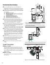
Vent Restriction
The GF 300 DV is equipped with an Exhaust Restrictor
Plate which enables you to regulate the flow of exhaust
gas. The plate prevents overly strong draft that can cause
poor combustion and weak flame picture. Follow the
guidelines below, and on the following pages, to deter-
mine the correct restrictor plate setting for your particu-
lar installation configuration.
Exhaust Restrictor
The Exhaust Restrictor is an adjustable shutter located at
the top right side of the firebox. It is adjusted by moving
a pivot pin into one of four positions. It is set in the FULLY
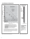
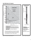
OPEN (D) position at the factory. See Fig. 7. The four
positions correlate to the termination zones (A,B,C,D)
diagramed in figures 9-12. Consult these Vent Window
diagrams on pages 10-11 to determine the setting you
should use.
Additional restriction may be needed depending the
overall vent height. If necessary, use Simpson Dura-Vent
Restrictor Disk #929.
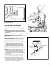
Adjusting Exhaust Restrictor Plate:
1. Use the Vent Window diagrams to determine which
setting position to use.
2. Remove the Top Plate.
3. Locate the pivot pin at the right side of the firebox top.
Use a 7 mm or 9/32 nut driver to loosen the nut on
the pivot pin and then push the pin to the left to
disengage it from the current factory-set position.
Move the pin forward and into the slot appropriate for
your specific vent configuration. See figs. 6 and 7.
4. Tighten the lock nut and replace the Top Plate.
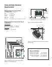
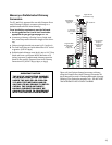
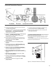
Venting Requirements
The Jøtul GF 300 DV gas stove may be installed with a
vertical or horizontal termination and must conform to
the configuration requirements described below.
This appliance is approved for use with vent systems
from the following manufacturers:
• Simpson Dura-Vent GS
• Amerivent Corporation
• Security Vent Ltd.
• Selkirk Metalbestos
Use parts of one manufacturer only - DO NOT MIX
VENT COMPONENTS FROM DIFFERENT MANUFACTURERS
IN THE SAME SYSTEM.
Installation of any components not manufactured or
approved by Jøtul or failure to meet all clearance require-
ments will void all warranties and could result in prop-
erty damage, bodily injury, or serious fire.
The approved vent configurations described in this
manual are derived from extensive testing under con-
trolled laboratory conditions. Gas appliance performance
can be negatively affected by variables present in the
installation environment, i.e: atmospheric pressure,
strong prevailing winds, adjacent structures and trees,
snow accumulation, etc. These conditions should be
taken into consideration by the installer and stove owner
when planning the vent system design.
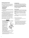
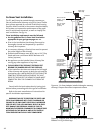
IMPORTANT
• JOINT SEALING REQUIREMENT: APPLY A 1/8” BEAD OF
HIGH-TEMPERATURE (750°F) SEALANT TO THE MALE
SECTION OF THE INNER VENT
PIPE. THE CEMENT SHOULD
FORM A SEAL BETWEEN THE
INNER AND OUTER PIPES.
• NEVER MODIFY ANY VENT-
ING COMPONENT, OR USE
ANY DAMAGED VENTING
PRODUCT.
• THE GAS APPLIANCE AND
VENT SYSTEM MUST BE
VENTED DIRECTLY TO THE
OUTSIDE OF THE BUILDING
AND NEVER ATTACHED TO A
CHIMNEY SERVING A SOLID
FUEL OR GAS BURNING
APPLIANCE. EACH DIRECT VENT GAS APPLIANCE MUST
HAVE ITS OWN SEPARATE VENT SYSTEM. COMMON
VENT SYSTEMS ARE PROHIBITED.
• IF VENTING SYSTEM IS DISASSEMBLED FOR ANY
REASON, REINSTALL PER THE INSTRUCTIONS PROVIDED
FOR THE INITIAL INSTALLATION.
Figure 5.