


17
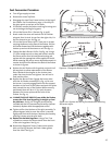
Fuel Conversion Procedure
1. Turn off gas supply to stove.
2. Remove the stove Top Plate.
3. Disengage the two Glass Frame Latches at the top of
the firebox. See illustration on page 5. Carefully lift
the glass panel up and out of the stove.
4. If installed, remove the Embers and Log Set using care
not to damage the fragile log parts.
5. Lift out the Burner Skirt- (Part 40, fig. 52 p.28).
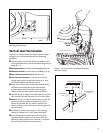
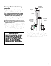
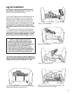
6. Reach under the stove and remove the Air Shutter
wingnut from its stud. As you face the right side, it is
the one closest to you. See fig. 22.
7. Lift out the Burner Plate: NOTE: There are no screws
securing the Burner to the floor of the firebox. Pull the
Air Shutter forward and lift the burner together with
shutter up and out of the stove as a unit. See fig. 23.
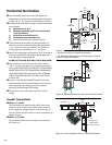
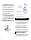
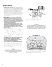
8. Change the Main Burner Orifice. See fig. 24. Using a
½” open ended wrench or deep-well socket remove
the burner orifice from its brass elbow housing and
replace with the appropriate orifice supplied in the kit.
While removing the orifice, use an adjustable wrench to
counter-lock the orifice elbow at the back of the firebox
as shown in fig. 24a.
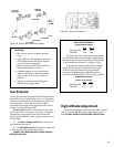
9. Replace the Air Shutter with its gasket and push it all
the way back to allow replacement of the Burner
Plate. Reattach the wingnut to the shutter stem
under the stove, but do not tighten. You will set its
final position later.
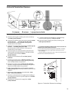
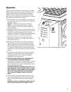
10. Replace the Burner Plate. Engage the burner tube
with the Air Shutter assembly as in fig. 25. Be sure
the burner is securely engaged with the two support
brackets at the front of the firebox and push the plate
back toward the rear of the firebox. When correctly
positioned, there will be 1/2” (13 mm) clearance
between the burner plate and the front of the
firebox. See fig. 25.
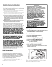
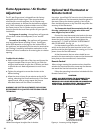
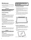
11 . CHANGE THE PILOT ORIFICE: From within the firebox,
remove the Pilot Head by pulling it straight up from
the pilot base. See fig. 26. Using the 4 mm hex key
included with the kit, unscrew the pilot orifice (counter-
clockwise). Replace with the appropriate orifice:
12. Tighten orifice into the base of the pilot assembly. To
prevent bypass leaks, be sure the orifice is secured
tightly and flush with the base. Replace pilot head by
pushing it down onto the pilot base.
13. Replace the Variable Regulator. Using a Torx T-20
screwdriver, remove the three screws from the front
of the valve regulator. See fig. 27.
14. Remove the Regulator Tower, Gasket, white plastic
disk, and Spring. Remove the black rubber gasket
from the valve. See fig. 27.
Figure 25. Correct Burner Position.
Figure 24. Change the Burner Orifice.
Burner Orifice
1/2”
clearance
Figure 23. Remove the Air Shutter and Burner as a unit.
Burner Plate
Air Shutter
Figure 24a. Counter-lock the orifice elbow while removing
the burner orifice.