


22
System Check
1. PURGING THE GAS LINE: When lighting the appli-
ance for the first time, it will take a few moments to
clear the gas line of air. Once this purge is complete,
the appliance will operate as described in the
lighting instructions. See the inside back cover of
this manual or the stove Rating Plate attached the
bottom of the stove. Subsequent burner starts will
not require purging the gas line unless the supply
line is shut off.
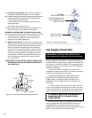
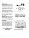
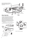
2. PILOT FLAME: You can monitor the pilot flame
through the view port located at the rear of the
Right Log. See fig. 37. The pilot flame should be
steady - not lifting or floating. The flame should be
blue in color around the pilot hood, with traces of
yellow toward the outer edges.
The pilot flame should engulf the top 3/8” of the
thermopile (to generate millivolt current) and the
top 1/8” of the thermocouple. The pilot flame
should project out of the pilot hood 1” at all three
ports. See fig. 37.
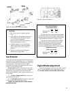
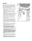
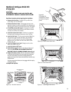
3. BURNER ADJUSTMENT: This stove is equipped with a
variable gas control valve that allows easy adjust-
ment of the flame height appearance and heat
output. To adjust the flame between the HI and
LOW setting, rotate the HI/LOW knob, located in the
center of the valve face. Flame height will adjust
approximately 1” to 2” between the LOW and HIGH
settings. See fig. 38.
NO SMOKE OR SOOT SHOULD BE PRESENT. CHECK
LOG PLACEMENT IF ANY SOOT OR SMOKE IS
PRESENT. IF SOOT OR SMOKE PERSISTS, THE AIR
SHUTTER MAY NEED TO BE ADJUSTED.
See Air Shutter/Flame Appearance section of this
manual for proper air shutter settings and adjust-
ments. Note: the more offsets there are in the vent
system, the greater the need for an air shutter
adjustment. See page 20.
Figure 38. Flame appearance on the “high” setting after
approximately 15 to 20 minutes burning.
WARNING:
AIR SHUTTER ADJUSTMENTS SHOULD ONLY BE
PERFORMED BY A QUALIFIED PROFESSIONAL
SERVICE TECHNICIAN.
CAUTION:
DO NOT ATTEMPT TO ALTER THE FLAME
APPEARANCE BY POSITIONING THE GAS
VALVE CONTROL IN ANY OTHER POSITION
OTHER THAN THE FULL “ON” POSITION.
1
(25mm)
3/8
(8mm)
Min.
1/8
(3mm)
Min.
Figure 37. Proper pilot flame appearance.