


368261-UIM-A-0508
8 Johnson Controls Unitary Products
SECTION III: FILTERS
FILTER INSTALLATION
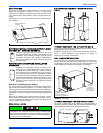
All applications require the use of a field installed filter. All filters and
mounting provision must be field supplied.
Filters must be installed external to the furnace cabinet. DO NOT
attempt to install filters inside the furnace.
NOTES:
1.Air velocity through throwaway type filters may not exceed 300 feet per
minute (91.4 m/min). All velocities over this require the use of high velocity
filters.
2.Do not exceed 1800 CFM using a single side return and a 16x25 filter. For
CFM greater than 1800, you may use two side returns or one side and the
bottom or one side return with a transition to allow use of a 20x25 filter.
SIDE RETURN
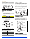
Locate the “L” shaped corner locators. These indicate the size of the cut-
out to be made in the furnace side panel. Refer to Figure 15, "Side
Return Cutout Markings".
Install the side filter rack following the instructions provided with that
accessory. If a filter(s) is provided at another location in the return air
system, the ductwork may be directly attached to the furnace side
panel.
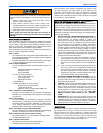
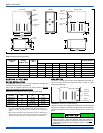
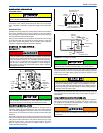
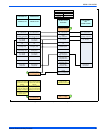
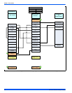
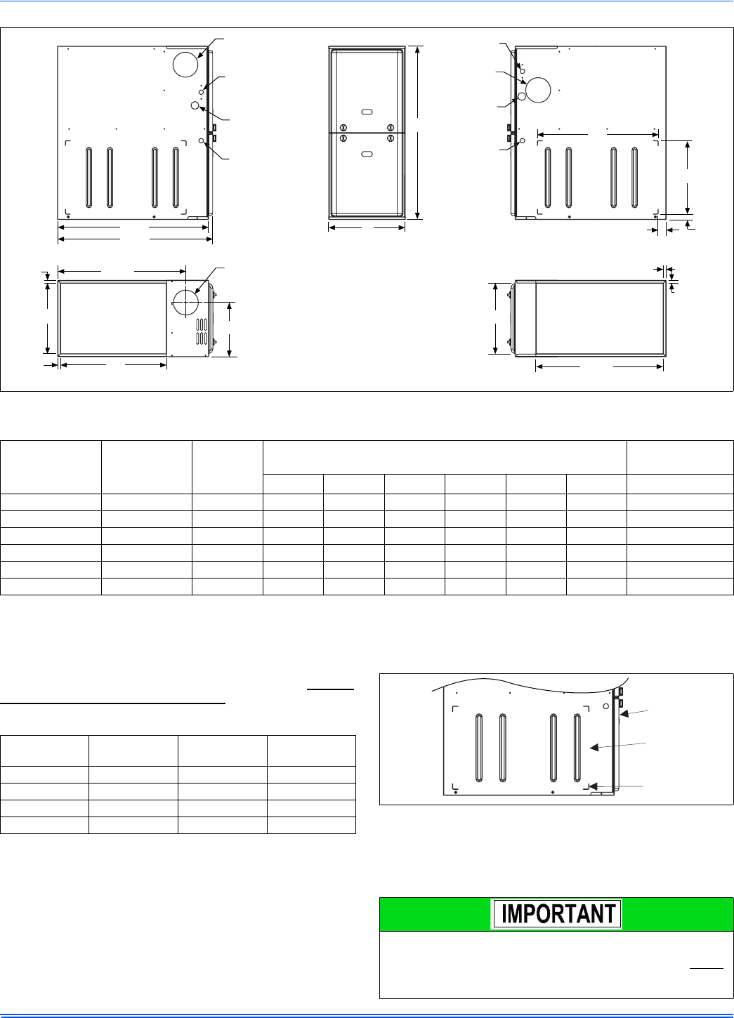
FIGURE 14: Dimensions
LEFT SIDE
RIGHT SIDE
.5”
.5”
Vent
Outlet
RETURN END
B
24.25”
29.5”
(For Claddeddoor add
appoximately anadditional .75”)
28.5”
Electrical
Entry
Gas Pipe
Entry
Thermostat
Wiring
FRONT
14”
1”
1.5”
23”
SUPPLY END
C
Vent
Outlet
24.38”
20”
.5”
B
Vent Outlet
Gas Pipe
Entry
Thermostat
Wiring
33”
A
.5”
Electrical
Entry
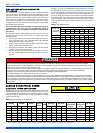
Table 3: Cabinet and Duct Dimensions
BTUH (kW)
Input
Nominal
CFM (m
3
/min)
Cabinet
Size
Cabinet Dimensions (Inches)
Approximate
Operating Weights
AA (cm)BB (cm)CC (cm) Lbs
60 (17.6) 1200 (34.0) A 14 1/2 36.8 13 1/2 34.3 10.3 26.2 94
80 (23.4) 1200 (34.0) B 17 1/2 44.4 16 1/2 41.9 11.8 29.9 103
80 (23.4) 1600 (45.3) C 21 53.3 20 50.8 13.6 34.5 114
100 (29.3) 1600 (45.3) C 21 53.3 20 50.8 13.6 34.5 118
100 (29.3) 2000 (56.6) C 21 53.3 20 50.8 13.6 34.5 122
120 (35.1) 2000 (56.6) C 21 53.3 20 50.8 15.8 40.1 129
Table 4: Recommended Filter Sizes (High Velocity 600 FPM)
CFM
(m³/min)
Cabinet
Size
Side
(in)
Bottom
(in)
1200 (34.0) A 16 x 25 14 x 25
1200 (34.0) B 16 x 25 16 x 25
1600 (45.3) C 16 x 25 20 x 25
2000 (56.6) C (2) 16 x 25 20 x 25
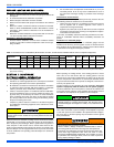
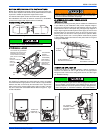
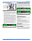
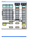
FIGURE 15: Side Return Cutout Markings
Some accessories such as electronic air cleaners and pleated
media may require a larger side opening. Follow the instructions
supplied with that accessory for side opening requirements. Do not
cut the opening larger than the dimensions shown in Figure 14,
"Dimensions".
Front of
Furnace
Corner
Markings
Side of
Furnace