


368261-UIM-A-0508
6 Johnson Controls Unitary Products
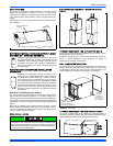
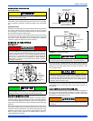
For horizontal left hand applications no conversion is required to an MC
coil when used with a downflow/horizontal furnace. A mounting plate,
supplied with every coil should always be installed on the side desig-
nated as top side. See Figures 4 & 5.
FURNACE ASSEMBLY - PC SERIES COILS
These upflow coils are designed for installation on top of upflow fur-
naces only.
If the coil is used with a furnace of a different size, use a 45° transition
to allow proper air distribution through the coil.
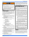
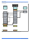
1. Position the coil casing over the furnace opening as shown in Fig-
ure 6, "PC Series Upflow Coil Installation".
2. Place the ductwork over the coil casing flange and secure.
3. Check for air leakage between the furnace and coil casing and
seal appropriately.
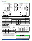
NOTE: Dimension “C” should be at least 2/3 of dimension “D”. See Fig-
ure 6, "PC Series Upflow Coil Installation"
CRITICAL COIL PROJECTION
The coil assembly must be located in the duct such that a minimum dis-
tance is maintained between the top of the coil and the top of the duct.
Refer to Table 2, "Coil Projection Dimensions - PC Series Coils".
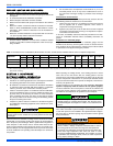
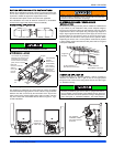
COIL / FURNACE ASSEMBLY - HC SERIES COILS
These coils are supplied ready to be installed in a right hand position or
a left hand position. When used in conjunction with a horizontal furnace
(blow through) application, the coil should be oriented with the opening
of the “A” coil closest to the furnace. See Figures 7.
NOTE: Each coil is shipped with an external tie plate that should be
used to secure the coil to the furnace. It should be installed on the back
side of the coil using the dimpled pilot holes. See Figures 7.
DOWNFLOW DUCT CONNECTORS
All downflow installations must use a suitable duct connector approved
by the furnace manufacturer for use with this furnace. The duct connec-
tors are designed to be connected to the rectangular duct under the
floor and sealed. Refer to the instructions supplied with the duct con-
nector for proper installation. Refer to the separate accessory parts list
at the end of these instructions for the approved accessory duct con-
nectors.
RESIDENTIAL AND MODULAR HOME UPFLOW
RETURN PLENUM CONNECTION
Return air may enter the furnace through the side(s) or bottom depend-
ing on the type of application. Return air may not be connected into the
rear panel of the unit.
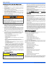
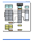
FIGURE 5: Horizontal Left Application
Do not drill any holes or drive any screws into the front duct
flange on the coil in order to prevent damaging coil tubing. See
Figure 6, "PC Series Upflow Coil Installation"
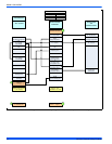
FIGURE 6: PC Series Upflow Coil Installation
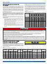
Table 2: Coil Projection Dimensions - PC Series Coils
COIL SIZE DIMENSION “C” INCH
PC18 3-1/2
PC24 4-1/2
PC30, PC32, PC35 4-1/2
PC42, PC43, PC36, PC37 5-1/2
PC48 6-1/2
PC60 9
Furnace
Mounting Plate
Flexible
Duct Collar
Do not drill
or Screw
this flange
Field
Fabricated
Ductwork
Upflow
Coil
Upflow
Furnace
Secondary
Drain
Primary
Drain
D
C
(Min)
Alternate
Drain Location
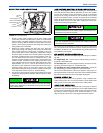
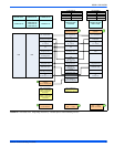
FIGURE 7: Horizontal Left or Right application (Right Shown)
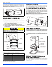
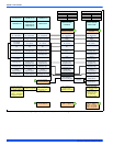
FIGURE 8: Combustible Floor Base Accessory
Use tie plate
supplied with coil
Air flow
Gas Furnace
FURNACE
WARMAIRPLENUM
WITH 1”FLANGES
FIBERGLASS
INSULATION
FIBERGLASSTAPE
UNDER FLANGE
COMBUSTIBLE FLOOR
BASEACCESSORY