


368261-UIM-A-0508
Johnson Controls Unitary Products 7
BOTTOM RETURN AND ATTIC INSTALLATIONS
Bottom return applications normally pull return air through a base plat-
form or return air plenum. Be sure the return platform structure or return
air plenum is suitable to support the weight of the furnace.
The internal bottom panel must be removed for this application.
Attic installations must meet all minimum clearances to combustibles
and have floor support with required service accessibility.
HORIZONTAL APPLICATION
ATTIC INSTALLATION
This appliance is certified for line contact when the furnace is installed
in the horizontal left or right position. The line contact is only permissible
between lines that are formed by the intersection of the top and two
sides of the furnace and the building joists, studs or framing. This line
may be in contact with combustible material. Refer to Figure 10, "Typi-
cal Attic Installation".
SUSPENDED FURNACE / CRAWL SPACE
INSTALLATION
The furnace can be hung from floor joists or installed on suitable blocks
or pad. Blocks or pad installations shall provide adequate height to
ensure the unit will not be subject to water damage. Units may also be
suspended from rafters or floor joists using rods, pipe angle supports or
straps. Angle supports should be placed at the supply air end and near
the blower deck. Do not support at return air end of unit. All four sus-
pension points must be level to ensure quite furnace operation. When
suspending the furnace use a secure platform constructed of plywood
or other building material secured to the floor joists. Refer to for typical
crawl space installation.
DOWNFLOW APPLICATION
To apply the furnace in a downflow position, it will be necessary to
rotate the vent blower 90° left or right so that the vent pipe passes
through the side of the furnace casing rather than the end. See Figure
12, "Downflow Venting".
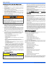
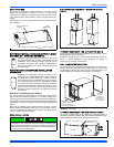
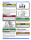
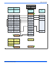
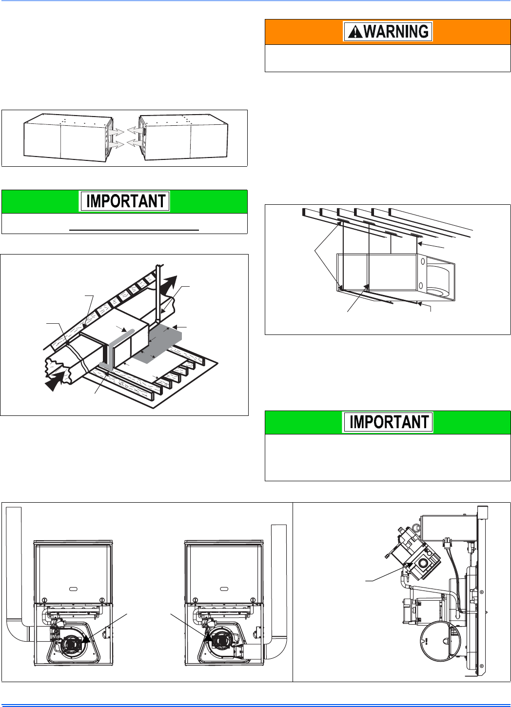
FIGURE 9: Horizontal Application
This furnace may be installed in a horizontal position on either side
as shown above. It must not be installed on its back.
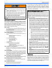
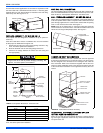
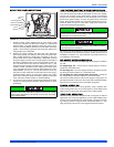
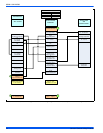
FIGURE 10: Typical Attic Installation
Return
Air
Sediment
Trap
GasPiping
Supply
Air
Vent (Maintain
required
clearances to
combustibles)
Line contact only permissible
between lines formed by the
intersection of furnace top
and two sides and building
joists, studs or framing
12”
30”MIN.
WorkArea
Filter rack
must be a minimum
distance
of 18” (45.7 cm)
from the
furnace
12”
Sheet metal in
front of furnace
combustion air
Openings is
Recommended
When a furnace is installed in an attic or other insulated space,
keep all insulating materials at least 12 inches (30.5 cm) away from
furnace and burner combustion air openings.
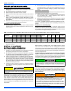
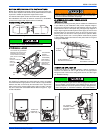
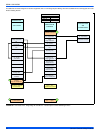
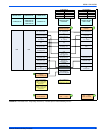
FIGURE 11: Typical Suspended Furnace / Crawl Space Installation
For modulating furnaces to be used in the downflow position, it is
necessary to rotate the gas valve so that it is upright when the fur-
nace is installed. Loosen the pipe union between the gas valve and
manifold, rotate the valve as far upward as it will go, and tighten the
union. See Figure 13, "Downflow Installation - Gas Valve Rotation".
Angle Iron
Bracket
6” Min. Between
Rod & Front of Furnace
1” Max. Between
Rod & Back of Furnace
Support
Bracket
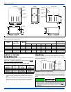
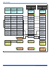
FIGURE 12: Downflow Venting FIGURE 13: Downflow Installation - Gas Valve Rotation
LEFT SIDE VENT
RIGHT SIDE VENT
Rotate vent
blower 90°
either way
For downflow
installation,rotate
gas valve upwards,
as shown