


368261-UIM-A-0508
Johnson Controls Unitary Products 21
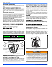
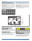
6. Remove the burner assembly. It should be possible to swing the
burner assembly out of the way without disconnecting the remain-
ing wires.
7. With the burner assembly out of the way, simply slide the NOx
screens out of the heat exchanger tubes and discard the screens.
8. Replace all components in reverse order. Reconnect all wiring.
GAS PIPING LEAK CHECK
It is recommended that when the gas supply is first connected to the
furnace, the ground union be loosened until the odor of gas is detected.
When gas is detected, immediately tighten the union and check for gas
leaks. Allow five minutes for any gas to dissipate before continuing with
the startup procedure. Be sure that proper ventilation is available to
dilute and carry away any vented gas.
With furnace in operation, check all of the pipe joints, gas valve connec-
tions and manual valve connections for leakage using an approved gas
detector, a non-corrosive leak detection fluid or other leak detection
methods. Take appropriate action to stop any leak. If a leak persists,
replace the faulty component.
The furnace and its equipment shutoff valve must be disconnected from
the gas supply during any pressure testing of that system at test pres-
sures in excess of 1/2 PSI (3.45 kPa).
The furnace must be isolated from the gas supply piping system by
closing the equipment shutoff valve during any pressure testing of the
gas supply system.
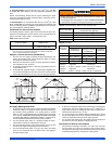
SETUP TEST MODE
During normal operation, the furnace input rate can vary between 50%
and 100% of full nameplate input, making it difficult to check for proper
operation. To help with the furnace startup process, the control has a
TEST MODE available that allows the furnace input rate to stay at a
constant input rate. To access this TEST MODE perform the following
sequence:
1. With power to the board on and with no thermostat calls (no call for
heating, cooling or continuous fan), push and hold the TEST but-
ton on the board for one second. The LED on the board will glow
red.
2. Release the TEST button. The LED on the board will flash a rapid
green signal, indicating that TEST MODE is activated.
3. Turn the thermostat to call for heat (R & W signal).
4. The furnace will light and operate at high (100%) firing rate. The
furnace firing rate should be checked at this level to confirm that
the furnace is not overfired or underfired.
5. To run the furnace at minimum rate (50%), press the ERROR but-
ton once. The LED will flash one green flash to confirm.
6. To run the furnace at a middle rate (70%), press the ERROR but-
ton twice within a five-second period. The LED will flash green two
times to confirm.
7. To again operate the furnace at maximum (100%) rate, press the
ERROR button three times within a five-second period. The LED
will flash green three times to confirm.
8. If the thermostat call for heat is removed, the LED will flash a rapid
green signal, indicating that the furnace is still in TEST MODE.
9. When startup tests are completed, turning off power to the board
will take the furnace out of TEST MODE and will restore normal
operation. The furnace will automatically return to normal opera-
tion after 150 minutes if power is not cycled.
CALCULATING THE FURNACE INPUT
(NATURAL GAS)
NOTE: Burner orifices are sized to provide proper input rate using natu-
ral gas with a heating value of 1030 BTU/Ft
3
(38.4 MJ/m
3
). If the heat-
ing value of your gas is significantly different, it may be necessary to
replace the orifices.
NOTE: DO NOT set manifold pressure less than 3.2 in wc or more than
3.8 in wc for natural gas at sea level. If manifold pressure is outside this
range, change main burner orifices.
NOTE: If orifice hole appears damaged or it is suspected to have been
redrilled, check orifice hole with a numbered drill bit of correct size.
Never redrill an orifice. A burr-free and sqaurely aligned orifice hole is
essential for proper flame characteristics.
Verify natural gas input rate by clocking meter.
1. Turn off all other gas appliances and pilots.
2. Run furnace for a minimum of 3 minutes in heating operation.
3. Measure time (in sec) for gas meter to complete 1 revolution and
note reading. The 2 cubic feet dial provides a more accurate mea-
surement of gas flow.
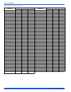
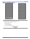
4. Refer to Table 10, "Gas Rate (CU FT/HR) at Full Input" for cubic
feet of gas per hour.
5. Multiply cubic feet per hour by heating valve (BTU/cu ft) to obtain
input.
If clocked rate does not match the input rate from the unit nameplate.
follow steps in next section to adjust the manifold pressure. Repeat
steps 2 - 5 until correct input is achieved.
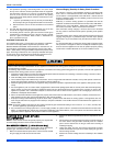
FIRE OR EXPLOSION HAZARD
Failure to follow the safety warnings exactly could result in serious
injury, death or property damage.
Never test for gas leaks with an open flame. Use a commercially
available soap solution made specifically for the detection of leaks
to check all connections. A fire or explosion may result causing
property damage, personal injury or loss of life.
Burner ignition may not be satisfactory on first startup due to resid-
ual air in the gas line or until gas manifold pressure is adjusted. The
ignition control will make three attempts to light before locking out.
DO NOT bottom out gas valve regulator adjusting screw. This can
result in unregulated manifold pressure and result in excess over-
fire and heat exchanger failures.
DO NOT bottom out gas valve regulator adjusting screw. This can
result in unregulated manifold pressure and result in excess over-
fire and heat exchanger failures.
Be sure to relight any gas appliances that were turned off at the
start of this input check.