


368261-UIM-A-0508
18 Johnson Controls Unitary Products
ACCESSORY CONNECTIONS
The furnace control will allow power-switching control of various acces-
sories.
ELECTRONIC AIR CLEANER CONNECTION
Two 1/4” (0.64 cm) spade terminals (EAC and NEUTRAL) for electronic
air cleaner connections are located on the control board. The terminals
provide 115 VAC (1.0 amp maximum) during circulating blower opera-
tion.
HUMIDIFIER CONNECTION
Two 1/4” (0.64 cm) spade terminals (HUM and NEUTRAL) for humidi-
fier connections are located on the control board. The terminals provide
115 VAC (1.0 amp maximum) during heating system operation.
A mounting hole is provided on the control panel next to the furnace
control board for mounting a humidifier transformer if required.
HUMIDISTAT CONNECTION
For better humidity control during cooling operation, an external humi-
distat may be used. When using a external humidistat, put the HUMI-
DISTAT jumper in the “YES” position. Connect the low voltage wiring as
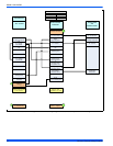
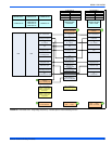
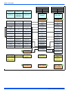
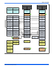
shown in Figures 20-25, Thermostat Charts.
SECTION VI: TWINNING AND STAGING
Twinning and staging is NOT allowed for modulating furnaces.
SECTION VII: VENT SYSTEM
VENT CONNECTIONS
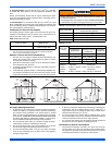
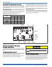
Figure 26, "Combustion Air Inducer" shows the furnace as it is shipped
from the factory. To convert to a horizontal or downflow position, remove
the four screws that secure the inducer assembly and rotate 90° being
careful not to damage the gasket. Reinstall screws. Remove cap from
appropriate vent outlet location on the cabinet cut insulation in cabinet
to same size as the hole provided and reinstall cap in the hole in the top
panel.
CATEGORY 1 - 450 F. MAX. VENT TEMP.
The venting system must be installed in accordance with Section 5.3,
Air for Combustion and Ventilation, of the National Fuel Gas Code
Z223.1/NFPA 54 (latest edition), or Sections 7.2, 7.3 or 7.4 of CSA
B149.1, National Gas and Propane Codes (latest edition) or applicable
provisions of the local building code and these instructions.
The furnace shall be connected to a type B vent connector, and
shall be connected to a type B vent only. The furnace shall not be
connected to a chimney flue serving a separate appliance
designed to burn solid fuel. Single-wall vent pipe is not allowed.
It is recommended that the appliance is installed in a location where the
space temperature is 32 °F (0°C) or higher. If the appliance is installed
in a location where the ambient temperature is below 32 °F (0°C), the
combustion byproducts could condense causing damage to the appli-
ance heat exchanger.
This appliance may be common vented with another gas appliance for
residential installations as allowed by the codes and standards listed in
these instructions.
VENTING
Category I venting consists of vertically venting one or more appliances
in B-vent or B-vent connectors. Type B-vent system extends in a gen-
eral vertical direction and does not contain offsets exceeding 45°. A
vent system having not more than one 60° offset is permitted.
VENTING INTO AN EXISTING CHIMNEY
This furnace may not be connected to any masonry chimney. However,
an existing masonry chimney may be used on as a chase through
which the metal vent pipe passes.
FAN-ASSISTED COMBUSTION SYSTEM
This appliance is equipped with an integral mechanical means to draw
products of combustion through the heat exchanger.
Ambient Combustion Air Supply
This type installation will draw the air required for combustion from
within the space surrounding the appliance and from areas or rooms
adjacent to the space surrounding the appliance. This may be from
within the space in a non-confined location or it may be brought into the
furnace area from outdoors through permanent openings or ducts. A
single, properly sized pipe from the furnace vent connector to the out-
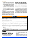
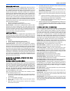
doors must be provided. For upflow models combustion air is brought
into the furnace through the unit top panel opening.
In downflow applications, do not block the combustion air inlet. The
furnace must be installed on a coil cabinet or subbase to allow com-
bustionair to enter the burner compartment.
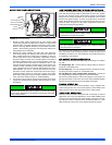
FIGURE 26: Combustion Air Inducer
COMBUSTION AIR INDUCER
90° 90°
Mounting Screw
(Remove)
Flue Transition
(Do Not Remove
)
Mounting Screw
(Remove)
Pressure
Switch
Pressure Switch
Tube Routing
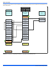
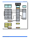
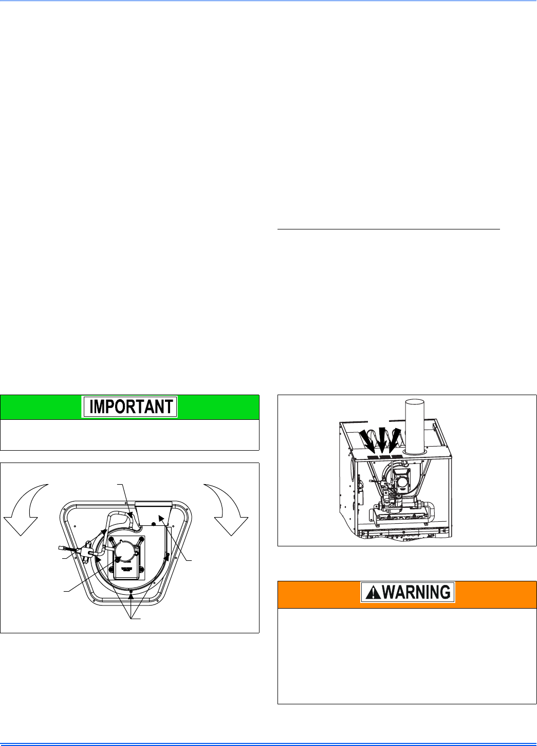
FIGURE 27: Combustion Airflow Path Through The Furnace Casing to
the Burner Compartment
This type of installation requires that the supply air to the appli-
ance(s) be of a sufficient amount to support all of the appliance(s)
in the area. Operation of a mechanical exhaust, such as an exhaust
fan, kitchen ventilation system, clothes dryer or fireplace may cre-
ate conditions requiring special attention to avoid unsatisfactory
operation of gas appliances. A venting problem or a lack of supply
air will result in a hazardous condition, which can cause the appli-
ance to soot and generate dangerous levels of CARBON MONOX-
IDE, which can lead to serious injury, property damage and / or
death.
COMBUSTION
AIR