


368261-UIM-A-0508
20 Johnson Controls Unitary Products
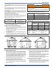
2. One permanent openings, commencing within 12 in (30.5 mm)of
the top of the enclosure shall be permitted where the equipment
has clearances of at least 1 in (2.54 cm) from the sides and back
and 6 in (15.24 cm) from the front of the appliance. The opening
shall communicate directly with the outdoors and shall have a min-
imum free area of:
a. 1 square in per 3000 Btu per hour (6.45 cm3 per 0.879 kW) of
the total input rating of all equipment located in the enclosure.
b. Not less than the sum of all vent connectors in the confined
space.
3. The duct shall be least the same cross-sectional area as the free
area of the air supply inlet opening to which it connects.
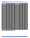
4. The blocking effects of louvers, grilles and screens must be given
consideration in calculating free area. If the free area of a specific
louver or a grille is not known. Refer to Table 7, "Estimated Free
Area" to estimate free area.
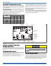
Ventilated Combustion Air
The ventilated attic space or a crawl space from which the combustion
air is taken must comply with the requirements specified in “AIR
SOURCE FROM OUTDOORS” in this instruction or in Section 5.3, Air
for Combustion and Ventilation of the National Fuel Gas Code, ANSI
Z223.1 (latest edition). This type installation requires two properly sized
pipes. One brings combustion air from a properly ventilated attic space
or crawl space and a second pipe that extends from the furnace vent
connection (top right of unit) to the exterior of the building.
Vent and Supply (Outside) Air Safety Check Procedure
For Category I furnaces, vent installations shall be in accordance with
Parts 7 and 11 of the National Fuel Gas Code, ANSI Z223.1/NFPA 54,
and or Section 7 and Appendix B of the CSA B149.1, Natural Gas and
Propane Installation Codes, the local building codes, furnace and vent
manufacture's instructions.
Multi-story or common venting systems are permitted and must be
installed in accordance with the National Fuel Gas Code, ANSI Z223.1/
NFPA 54 and / or the CSA B149.1, Natural Gas and Propane Installa-
tion Codes, local codes, and the manufacture's instructions.
Vent connectors serving Category I furnaces shall not be connected
into any portion of mechanical draft systems operating under positive
pressure.
Horizontal portions of the venting system shall be supported to prevent
sagging using hangers or perforated straps and must slope upwards
not less than 1/4" per foot (0.635 cm/m) from the furnace to the vent ter-
minal.
It is recommended that you follow the venting safety procedure below.
This procedure is designed to detect an inadequate ventilation system
that can cause the appliances in the area to operate improperly causing
unsafe levels of Carbon Monoxide or an unsafe condition to occur.
SECTION VIII: START-UP AND
ADJUSTMENTS
NOTE: In order that this furnace will operate properly, it is required that
all of the startup procedures in this section be followed.
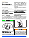
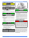
NOx SCREEN REMOVAL (Lo-NOx Models Only)
If the furnace is equipped with NOx screens and is to be used with LP
(propane) gas, the screens must be removed prior to start-up.
1. Make sure that the electrical power to the unit is turned off and that
the gas supply is turned off at the shut-off valve.
2. Remove the blower compartment and burner compartment access
doors.
3. Disconnect the gas supply piping at the union to permit removal of
the entire burner and gas control assembly from the vestibule
panel. Use the wrench boss on the gas valve when removing or
installing the piping.
4. Unplug the igniter from the wire harness. Disconnect the flame
sensor wires located on top of the air shield. Unplug the gas valve
from the wiring harness.
5. Remove the screws holding the burner assembly to the vestibule
panel.
CARBON MONOXIDE POISONING HAZARD
Failure to follow the steps outlined below for each appliance connected to the venting system being placed into operation could result in carbon-
monxide poisoning or death.
The following steps shall be followed for each appliance connected to the venting system being placed into operation, while all other appliances
connected to the venting system are not in operation:
1. Inspect the venting system for proper size and horizontal pitch. Determine that there is no blockage, restriction, leakage, corrosion or other
deficiencies, which could cause an unsafe condition
2. Close all building doors and windows and all doors.
3. Turn on clothes dryers and TURN ON any exhaust fans, such as range hoods and bathroom exhausts, so they shall operate at maximum
speed. Open the fireplace dampers. Do not operate a summer exhaust fan.
4. Follow the lighting instructions. Place the appliance being inspected in operation. Adjust thermostat so the appliance shall operate contin-
uously.
5. Test each appliance (such as a water heater) equipped with a draft hood for spillage (down-draft or no draft) at the draft hood relief opening
after 5 minutes of main burner operation. Appliances that do not have draft hoods need to be checked at the vent pipe as close to the
appliance as possible. Use a combustion analyzer to check the CO2 and CO levels of each appliance. Use a draft gauge to check for a
downdraft or inadequate draft condition.
6. After it has been determined that each appliance properly vents when tested as outlined above, return doors, windows, exhaust fans, fire-
place dampers and any other gas burning appliance to their normal condition.
7. If improper venting is observed during any of the above tests, a problem exists with either the venting system or the appliance does not
have enough combustion air (Supply Air from outside) to complete combustion. This condition must be corrected before the appliance can
function safely.
NOTE: An unsafe condition exists when the CO reading exceeds 40 ppm and the draft reading is not in excess of - 0.1 in. W.C. (-25 kPa) with
all of the appliance(s) operating at the same time.
8. Any corrections to the venting system and / or to the supply (outside) air system must be in accordance with the National Fuel Gas Code
Z223.1 or CAN/CGA B149.1 Natural Gas and Propane Installation Code (latest editions). If the vent system must be resized, follow the
appropriate tables in Appendix G of the above codes or for this appliance.