


368261-UIM-A-0508
Johnson Controls Unitary Products 11
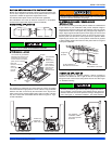
SUPPLY VOLTAGE CONNECTIONS
1. Provide a power supply separate from all other circuits. Install
overcurrent protection and disconnect switch per local/national
electrical codes. The switch should be close to the unit for conve-
nience in servicing. With the disconnect or fused switch in the OFF
position, check all wiring against the unit wiring label. Refer to the
wiring diagram in this instruction.
2. Remove the screws retaining the wiring box cover. Route the
power wiring through the opening in the unit into the junction box
with a conduit connector or other proper connection. In the junc-
tion box there will be 3 wires, a Black Wire, a White Wire. Connect
the power supply as shown on the unit-wiring label on the inside of
the blower compartment door or the wiring schematic in this sec-
tion. The black furnace lead must be connected to the L1 (hot)
wire from the power supply. The white furnace screw must be con-
nected to neutral. Connect the power supply ground to the green
screw (equipment ground) An alternate wiring method is to use a
field provided 2” (5.1 cm) x 4” (10.2 cm) box and cover on the out-
side of the furnace. Route the furnace leads into the box using a
protective bushing where the wires pass through the furnace
panel. After making the wiring connections replace the wiring box
cover and screws. Refer to Figure 19, "Electrical Wiring".
3. The furnace's control system requires correct polarity of the power
supply and a proper ground connection. Refer to Figure 19, "Elec-
trical Wiring"
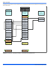
LOW VOLTAGE CONTROL WIRING CONNECTIONS
Install the field-supplied thermostat by following the instructions that
come with the thermostat. With the thermostat set in the OFF position
and the main electrical source disconnected, connect the thermostat
wiring from the wiring connections on the thermostat to the terminal
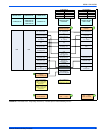
board on the ignition module, as shown in Figures 20-25, Thermostat
Charts. Electronic thermostats may require the common wire to be con-
nected as shown in Figure 16, "Gas Valve". Apply strain relief to ther-
mostat wires passing through cabinet.
The 24-volt, 40 VA transformer is sized for the furnace components
only, and should not be connected to power auxiliary devices such as
humidifiers, air cleaners, etc. The transformer may provide power for an
air conditioning unit contactor.
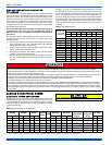
AIR CONDITIONER CONNECTIONS
This furnace may be used with single-stage or two-stage air condition-
ing units.
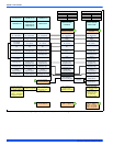
For Single-Stage A/C - Connect the low voltage wiring as shown in
Figures 20, Thermostat Chart.
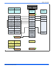
For Two-Stage A/C - Use a two-stage thermostat, connect the low volt-
age wiring as shown in Figures 21, Thermostat Chart.
For Two-Stage A/C using a Single-Stage Thermostat - connect the
low voltage wiring as shown in Figures 21, Thermostat Chart.
This furnace control board can control a two-stage A/C using only a sin-
gle-stage thermostat. In this case, the furnace control switches between
high cool and low cool based on the calculated cooling load.
ZONING OPERATION
This furnace may be used in zoning systems, using a separate after-
market zoning control. For use in zoned systems, put the ZONE CON-
TROL jumper on the furnace control board in the “YES” position.
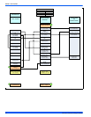
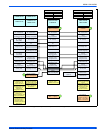
HEAT PUMP OPERATION
This furnace may be used in conjunction with a heat pump in dual fuel
applications. For heat pump applications, put the HEAT PUMP jumper
on the furnace control board in the “YES” position. Connect the low volt-
age wiring as shown in Figures 20-25, Thermostat Charts. If a two-
stage heat pump is to be used, a two-stage thermostat is required.
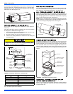
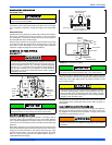
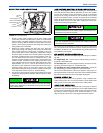
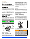
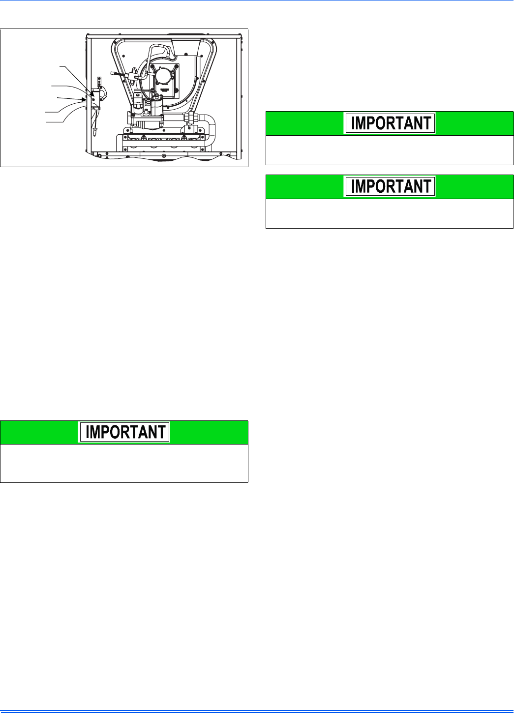
FIGURE 19: Electrical Wiring
The power connection leads and wiring box may be relocated to the
left side of the furnace. Remove the screws and cut wire tie holding
excess wiring. Reposition on the left side of the furnace and fasten
using holes provided.
Electrical Entry
Junction
Box
L1-Hot
Neutral
Connect ground
lead to screw
BLK
WHT
Set the heat anticipator in the room thermostat to 0.4 amps. Setting
it lower will cause short cycles. Setting it higher will cause the room
temperature to exceed the set points.
Some electronic thermostats do not have adjustable heat anticipa-
tors. They should be set to six cycles per hour. Follow the thermo-
stat manufacturer's instructions.