


368261-UIM-A-0508
4 Johnson Controls Unitary Products
FURNACE LOCATION AND CLEARANCES
The furnace shall be located using the following guidelines:
1. Where a minimum amount of air intake/vent piping and elbows will
be required.
2. As centralized with the air distribution as possible.
3. Where adequate combustion air will be available.
4. Where it will not interfere with proper air circulation in the confined
space.
5. Where the outdoor vent terminal will not be blocked or restricted.
Refer to “VENT CLEARANCES” located in SECTION VII of these
instructions. These minimum clearances must be maintained in
the installation.
6. Where the unit will be installed in a level position with no more than
1/4” (6.4 mm) slope side-to-side and front-to-back.
Installation in freezing temperatures:
1. Furnace shall be installed in an area where ventilation facilities
provide for safe limits of ambient temperature under normal oper-
ating conditions.
2. Do not allow return air temperature to be below 55º F (13° C) for
extended periods. To do so may cause condensation to occur in
the main heat exchanger, leading to premature heat exchanger
failure.
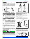
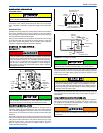
Clearances for access/service:
Ample clearances should be provided to permit easy access to the unit.
The following minimum clearances are recommended:
1. Twenty-four (24) inches (61 cm) between the front of the furnace
and an adjacent wall or another appliance, when access is
required for servicing and cleaning.
2. Eighteen (18) inches (46 cm) at the side where access is required
for passage to the front when servicing or for inspection or replace-
ment of flue/vent connections.
In all cases, accessibility clearances shall take precedence over clear-
ances for combustible materials where accessibility clearances are
greater.
Installation in a residential garage:
A gas-fired furnace for installation in a residential garage must be
installed so the burner(s) and the ignition source are located not less
than 18 inches (46 cm) above the floor, and the furnace must be located
or protected to avoid physical damage by vehicles.
SECTION II: DUCTWORK
DUCTWORK GENERAL INFORMATION
The duct system’s design and installation must:
1. Handle an air volume appropriate for the served space and within
the operating parameters of the furnace specifications.
2. Be installed in accordance of National Fire Protection Association
as outlined in NFPA standard 90B (latest editions) or applicable
national, provincial, state, and local fire and safety codes.
3. Create a closed duct system. For residential and Non-HUD Modu-
lar Home installations, when a furnace is installed so that the sup-
ply ducts carry air circulated by the furnace to areas outside the
space containing the furnace, the return air shall also be handled
by a duct(s) sealed to the furnace casing and terminating outside
the space containing the furnace.
4. Complete a path for heated or cooled air to circulate through the
air conditioning and heating equipment and to and from the condi-
tioned space.
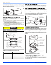
When the furnace is used with a cooling coil, the coil must be installed
parallel with, or in the supply air side of the furnace to avoid condensa-
tion in the primary heat exchanger. When a parallel flow arrangement is
used, dampers or other means used to control airflow must be ade-
quate to prevent chilled air from entering the furnace. If manually oper-
ated, the damper must be equipped with means to prevent the furnace
or the air conditioner from operating unless the damper is in full heat or
cool position.
When replacing an existing furnace, if the existing plenum is not the
same size as the new furnace then the existing plenum must be
removed and a new plenum installed that is the proper size for the new
furnace. If the plenum is shorter than 12” (30.5 cm) the turbulent air flow
may cause the limit controls not to operate as designed, or the limit con-
trols may not operate at all.
The duct system is a very important part of the installation. If the duct
system is improperly sized the furnace will not operate properly.
The ducts attached to the furnace plenum, should be of sufficient size
so that the furnace operates at the specified external static pressure
and within the air temperature rise specified on the nameplate.
If a matching cooling coil is used, it may be placed directly on the fur-
nace outlet and sealed to prevent leakage. If thermoplastic evaporator
‘A’ coil drain pans are to be installed in the upflow/horizontal configura-
tion, then extra 2” minimum spacing may be needed to ensure against
drain pan distortion.
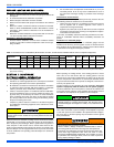
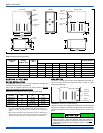
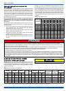
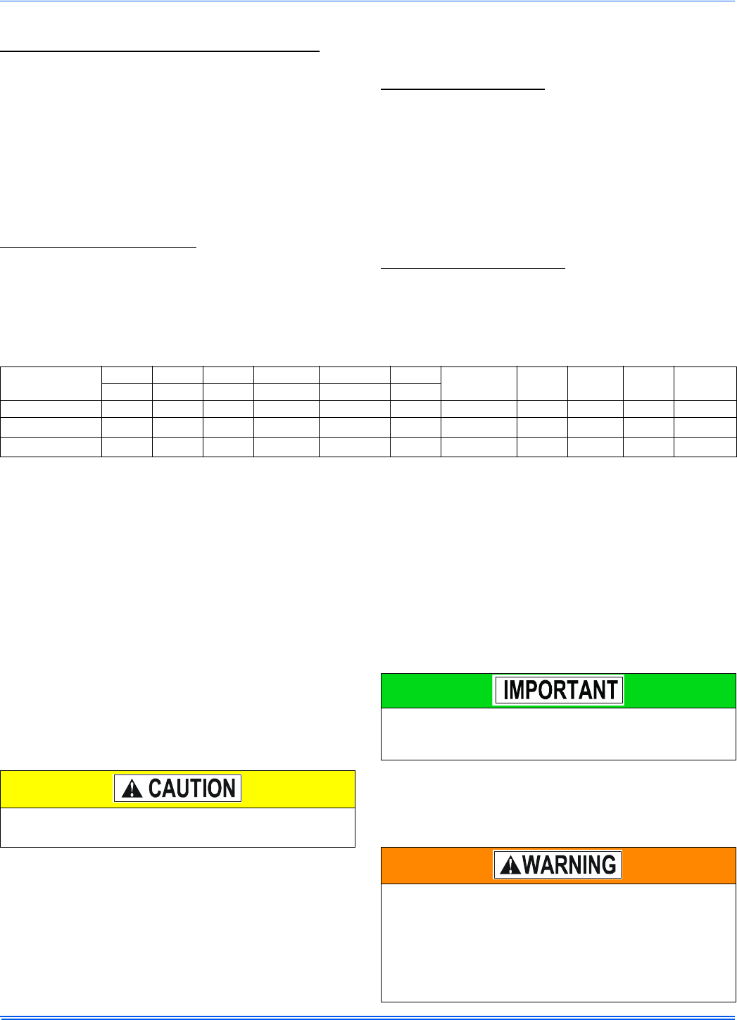
Table 1: Unit Clearances to Combustibles (All Dimensions in Inches, and All Surfaces Identified with the Unit in an Upflow Configuration)
Application
Top Front Rear Left Side Right Side Flue
Floor/
Bottom
Closet Alcove Attic
Line
Contact
In. (cm) In. (cm) In. (cm) In. (cm) In. (cm) In. (cm)
Upflow B-Vent 1 (2.5) 3 (7.6) 0 (0.0) 0 (0.0) 0 (0.0) 1 (2.5) Combustible Yes Yes Yes No
Downflow B-Vent 1 (2.5) 3 (7.6) 0 (0.0) 0 (0.0) 0 (0.0) 1 (2.5)
1 (25.4)
1
1.Special floor base or air conditioning coil required for use on combustible floor.
Yes Yes Yes No
Horizontal B-Vent 1 (2.5) 3 (7.6) 0 (0.0) 0 (0.0) 0 (0.0) 1 (2.5) Combustible No Yes Yes
Yes
2
2.Line contact only permitted between lines formed by the intersection of the rear panel and side panel (top in horizontal position) of the furnace jacket and building
joists, studs or framing.
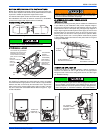
The cooling coil must be installed in the supply air duct, down-
stream of the furnace. Cooled air may not be passed over the heat
exchanger.
The minimum plenum height is 12” (30.5 cm). The furnace will not
operate properly on a shorter plenum height. The minimum recom-
mended rectangular duct height is 4 inches (10 cm) attached to the
plenum.
The duct system must be properly sized to obtain the correct airflow
for the furnace size that is being installed.
Refer to Table 6, "Ratings & Physical / Electrical Data" or the fur-
nace rating plate for the correct rise range and static pressures.
If the ducts are undersized, the result will be high duct static pres-
sures and/or high temperature rises which can result in a heat
exchanger OVERHEATING CONDITION. This condition can result
in premature heat exchanger failure, which can result in personal
injury, property damage, or death.