


368261-UIM-A-0508
24 Johnson Controls Unitary Products
ADJUSTMENT OF FAN CONTROL SETTINGS
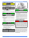
Cooling - The airflow delivered by the furnace during cooling operation
can be adjusted to match the cooling capacity of the A/C condensing
unit. This is done by moving the COOL jumper on the control board to
give the desired airflow.
Do not move the motor wires to different positions on the
furnace control board!
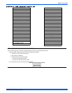
The jumper has four positions, which will deliver sufficient airflow in
cooling mode for the cooling capacities shown in the table below. The
CFM delivery on each jumper position is shown in Table 13.
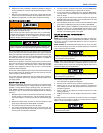
Continuous Fan Operation - The airflow delivered by the furnace dur-
ing continuous fan operation can be adjusted as desired. This is done
my moving the FAN jumper on the control board to give the desired air-
flow.
Do not move the motor wires to different positions on the
furnace control board!
The jumper has three positions. The "A" position delivers maximum air-
flow, 100% of the blower capacity. Position "B" delivers approximately
70% of the blower capacity. And Position "C" delivers minimum airflow,
approximately 40% of the blower capacity.
SECTION IX: SAFETY CONTROLS
CONTROL CIRCUIT FUSE
A 3-amp fuse is provided on the control circuit board to protect the 24-
volt transformer from overload caused by control circuit wiring errors.
This is an ATO 3, automotive type fuse and is located on the control
board.
BLOWER DOOR SAFETY SWITCH
This unit is equipped with an electrical interlock switch mounted in the
burner compartment. This switch interrupts all power at the unit when
the panel covering the blower compartment is removed.
Electrical supply to this unit is dependent upon the panel that covers the
blower compartment being in place and properly positioned.
ROLLOUT SWITCH CONTROLS
These controls are mounted on the burner assembly. If the temperature
in the burner area exceeds its set point, the ignition control and the gas
valve are de-energized. The operation of this control indicates a mal-
function in the combustion air blower, heat exchanger or a blocked vent
pipe connection. Corrective action is required. These are manual reset
controls that must be reset before operation can continue.
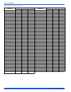
TABLE 13:
Cooling Airflow - A/C Capacity in Tons
Models
Jumper Position
ABCD
60/1200 3 2-1/2 2 1-1/2
80/1200 3 2-1/2 2 1-1/2
80/1600 4 3-1/2 3 2-1/2
100/1600 4 3-1/2 3 2-1/2
100/2000 5 4 3-1/2 3
120/2000 5 4 3-1/2 3
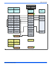
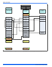
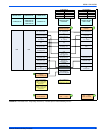
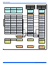
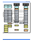
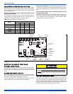
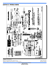
FIGURE 30: Furnace Control Board
DIAGNOSTIC
LIGHT
LOW
VOLTAGE
TERMINALS
HUMIDISTAT
JUMPER
LASTERROR
BUTTON
TEST
BUTTON
CONTINUOUS
FANSPEED
JUMPER
COOLING
SPEED
JUMPER
HEATPUMP
JUMPER
ZONING
JUMPER
EAC
TERMINALS
HUMIDIFIER
TERMINALS
ZONE
CONTROL
NO
YES
EXT
PRESSURE
SENSOR
A-COIL
TEMP
SENSOR
TEST
BUTTON
ERROR
BUTTON
120VAC 120VAC
XFORMER
NEUTRAL
NEUTRAL
XFORMER
GROUND
WHITE
BLOWER
BLACK
BLUE
BLOWER
BLOWER
BLOWER
YELLOW
BLOWER
RED
24VAC
MODULATECOIL
GASVALVE
PRIMARY
LIMIT
AUX
LIMIT
AIR
SW
TEMP
SENSOR
HUMIDIFIER
NEUTRAL
HOT
INDUCER
NEUTRAL
HOT
IGNITER
NEUTRAL
HOT
NEUTRAL
HOT
EAC
EAC
FLAMEROD
FLAMEVOLTAGE
IDPLUG
HEATPUMP
HUMIDISTAT
YES NO
YES NO
ATR
CONTFAN
COOL
NOM
-10F
+10F
LMH
L
ML
MH
H
LO COMP
HI COMP
O
DHUM
Y1
Y/Y2
W
R
G
C
Main power to the unit must still be interrupted at the main power
disconnect switch before any service or repair work is to be done to
the unit. Do not rely upon the interlock switch as a main power dis-
connect.
Blower and burner must never be operated without the blower
panel in place.