


368261-UIM-A-0508
Johnson Controls Unitary Products 25
PRESSURE CONTROLS
Pressure Sensor - This furnace is equipped with a pressure sensor in
the burner compartment near the combustion blower. This sensor mon-
itors combustion airflow through furnace and piping systems. If any of
the conditions listed below are detected by the pressure sensor, the
control board will prevent a hazardous condition from occurring by
speeding up the combustion blower motor in order to maintain ade-
quate combustion airflow. If the combustion blower is already turning at
full speed, the furnace control will then start reducing the input to the
furnace in order to maintain proper combustion with the amount of com-
bustion airflow available. If there is not enough combustion air available
to give proper combustion even at the minimum input rate (50%), the
control will close the gas valve and shut off the burners. The sensor will
detect the following conditions.
1. Blockage of vent piping or vent terminal
2. Failure of combustion air blower motor or blower wheel.
Pressure Switch - This furnace is equipped with a pressure switch
mounted on the furnace vestibule panel. This switch monitors the flow
through the vent system. The switch will close at the beginning of each
cycle when adequate combustion airflow is established. However, this
switch may be open under certain conditions when the burners are lit.
The pressure sensor is the primary flow sensor.
LIMIT CONTROLS
Limit Switch - This furnace is equipped with a high temperature limit
control mounted to the left side of the furnace vestibule panel. This limit
switch will open and shut off gas to the burners if it detects excessive air
temperature in the furnace, which can be caused by any of the following
conditions:
1. Dirty filter
2. Failure of the circulating blower motor or wheel
3. Too many supply or return registers closed or blocked.
Temperature Sensor - This furnace is also equipped with a tempera-
ture sensor mounted to the left side of the vestibule panel, near the limit
switch. This sensor monitors the temperature of the air being supplied
to the home. If the sensor detects air temperature higher than normal,
the furnace control will first speed up the circulating blower motor in
order to try to increase the amount of airflow being delivered, thereby
reducing the air temperature. If the blower motor is already turning at
full speed, the control will then start reducing the input to the furnace to
try to reduce the air temperature. If the supply air temperature is too
high even at the minimum input rate (50%), the control will close the
gas valve and shut off the furnace.
SECTION X: NORMAL OPERATION AND
DIAGNOSTICS
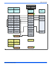
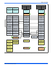
NORMAL OPERATION SEQUENCE
The furnace control calculates the optimum firing rate each time the
wall thermostat R and W contacts close or open (at the beginning and
at the end of each call for heat) based on information from the thermo-
stat and past demand. UNLIKE CONVENTIONAL SYSTEMS, THE
WALL THERMOSTAT DOES NOT SIMPLY TURN THE FURNACE ON
AND OFF. THE FURNACE CONTROL CALCULATES THE DEMAND
AND MAY CONTINUE TO FIRE THE FURNACE DURING PORTIONS
OF THE THERMOSTAT "OFF" CYCLE.
When the wall thermostat R and W contacts close, indicating a call for
heat, the following sequence occurs:
1. The inducer is energized and ramps up its speed until airflow is
proven by the pressure switch and by the pressure sensor on the
control board.
2. The hot surface ignitor is energized.
3. After a 17-20 second igniter heatup, the gas valve opens and the
burners light.
4. When the control senses that flame is present, the circulating
blower starts at low speed.
5. The furnace fires at 70% of full rate for 30-45 seconds, then drops
to the minimum (50%) firing rate.
6. The firing rate is automatically adjusted to meet demand, increas-
ing gradually to maximum (100%) firing rate if the thermostat is not
satisfied within a defined time.
7. When the thermostat R and W contacts open (thermostat is satis-
fied) the furnace control recalculates the demand and a new firing
rate.
A. If demand exceeds the minimum firing rate, the burners will
continue to fire at a recalculated reduced firing rate, decreas-
ing if the thermostat remains off for a defined time.
b. If demand does not exceed the minimum firing rate, the burn-
ers will shut off immediately.
8. After the burners shut off, the circulating blower will continue to run
until the temperature sensor detects that the supply air tempera-
ture has dropped to the desired level, which should take from 30 to
90 seconds.
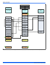
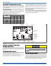
FURNACE CONTROL DIAGNOSTICS
This furnace has built-in self-diagnostic capability. If a system problem
occurs, a flashing LED shows a fault code. The LED can flash red,
green or amber to indicate various conditions. The LED is located on
the furnace control board and can be seen through the clear view port
in the lower door of the furnace. To indicate an error condition, the LED
will turn on for 1/4 second and off for 1/4 second. The pattern will be
repeated the number of times equal to the flash code. For instance, a
"six flash code" will be indicated by the LED turning on and off six times.
There will be a two second off period between each set of flashes. The
flash codes and an indication of their likely causes are listed below:
STEADY OFF - No 24V power to board. Check the 24 volt control cir-
cuit fuse on the board. Check the circuit breaker or fuse on the 115 volt
supply power to the furnace. Check that the 24 volt transformer.
One Green Flash - Normal Operation with no call for heat.
Two Green Flashes - Indicator for "No error codes in memory". See
Diagnostic Fault Code Storage and Retrieval section below.
Three Green Flashes - Indicator for "Error codes cleared from mem-
ory". See Diagnostic Fault Code Storage and Retrieval section below.
Rapid Green Flash - Control is in "Factory Speedup" mode. This mode
is used only during factory run-testing of the furnace. To stop this mode,
cycle power to the furnace off and then back on.
One Amber Flash - Normal operation with call for cooling.
Two Amber Flashes - Normal operation with call for heat.
Three Amber flashes - Normal operation, burner is on at end of heat-
ing cycle after wall thermostat has been satisfied.
Four Amber Flashes - Heating capacity is reduced due to restriction in
the circulating air system. Check for dirty filter or closed registers.
Five Amber Flashes - Heating capacity is reduced due to restriction in
the combustion air or vent system. Check for blocked vent/air pipe or
clogged condensate drain. Above 4,000 feet altitude, this may also indi-
cate automatic, normal derating for altitude. See page 7 for additional
high altitude information.
Six Amber Flashes - (Heat Pump applications only) Normal operation
with call for heat pump heating.
Rapid Amber Flash - Low flame sense current. Check for dirty or mis-
located flame sensor rod.
One Red Flash - Flame is present with no power being supplied to gas
valve. This can be caused by a gas valve that is slow to close or that
leaks gas through to the burners.
Two Red Flashes - Stuck closed pressure switch. The control confirms
that the pressure switch contacts are open at the beginning of each
cycle. This could be caused by a faulty pressure switch or by mis-wiring
of the pressure switch.