


8
icos - Installation & Servicing
GENERAL
SAFE HANDLING OF SUBSTANCES
Care should be taken when handling the boiler insulation
panels, which can cause irritation to the skin. No asbestos,
mercury or CFCs are included in any part of the boiler or its
manufacture.
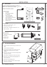
LOCATION OF BOILER
The boiler must be installed on a flat and vertical wall, capable
of adequately supporting the weight of the boiler and any
ancillary equipment.
The boiler may be fitted on a combustible wall and insulation
between the wall and the boiler is not necessary, unless
required by the local authority.
For electrical safety reasons there must be no access from the
back of the boiler.
The boiler must not be fitted outside.
Timber Framed Buildings
If the boiler is to be fitted in a timber framed building it should
be fitted in accordance with the Institute of Gas Engineering
document IGE/UP/7:1998.
Bathroom Installations
This appliance is rated IP20.
The boiler may be installed in any room or internal space,
although particular attention is drawn to the requirements of the
current IEE (BS.7671) Wiring Regulations and, in Scotland, the
electrical provisions of the building regulations applicable in
Scotland, with respect to the installation of the boiler in a room
or internal space containing a bath or shower. For Ireland
reference should be made to the current ETCI rules for
electrical installations and I.S.813:2002.
If the appliance is to be installed in a room containing a bath or
shower then, providing water jets are not going to be used for
cleaning purposes (as in communal baths/showers), the
appliance can be installed in Zone 3, as detailed in BS.7671.
Compartment Installations
A compartment used to enclose the boiler should be designed
and constructed specially for this purpose.
An existing cupboard or compartment may be used, provided
that it is modified for the purpose.
In both cases details of essential features of cupboard /
compartment design, including airing cupboard installation,
are to conform to the following:
z BS. 6798. (No cupboard ventilation is required - see “Air
Supply” for details).
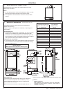
z The position selected for installation MUST allow adequate
space for servicing in front of the boiler.
z For the minimum clearances required for safety and
subsequent service see the wall mounting template and
Frame 2. In addition, sufficient space may be required to
allow lifting access to the wall mounting plate.
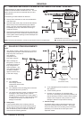
GAS SUPPLY
The local gas supplier should be consulted, at the installation
planning stage, in order to establish the availability of an
adequate supply of gas. An existing service pipe must NOT be
used without prior consultation with the local gas supplier.
The boiler MUST be installed on a gas supply with a governed
meter only.
A gas meter can only be connected by the local gas supplier or
by a CORGI registered engineer. In IE by a Competent Person.
An existing meter should be checked, preferably by the gas
supplier, to ensure that the meter is adequate to deal with the
rate of gas supply required.
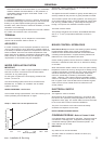
N.B. The principle of the 1:1 gas valve ensures that the icos
HE range is able to deliver it’s full output at inlet pressures
down to 14mb. However if dynamic pressures below 20mb are
experienced ensure this is adequate for ALL other gas
appliances in the property.
IMPORTANT.
Installation pipes MUST be fitted in accordance with BS. 6891.
In IE refer to I.S.813:2002. Pipework from the meter to the boiler
MUST be of an adequate size, i.e. no longer than 20m and not
less than 15mm O.D.
The complete installation MUST be tested for gas soundness
and purged as described in the above code.
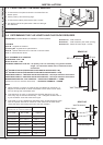
FLUE INSTALLATION
Pluming will occur at the terminal so terminal positions which
would cause a nuisance should be avoided.
The flue must be installed in accordance with the
recommendations of BS.5440-1:2000. In IE refer to I.S.813:2002.
The following notes are intended for general guidance.
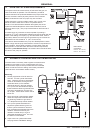
1. The boiler MUST be installed so that the terminal is exposed
to external air.
2. It is important that the position of the terminal allows the free
passage of air across it at all times.
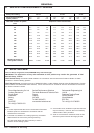
3. Minimum acceptable spacing from the terminal to
obstructions and ventilation openings are specified in Table 3.
4. Where the lowest part of the terminal is fitted less than 2m
(6'6") above a balcony, above ground or above a flat roof to
which people have access, then the terminal MUST be
protected by a purpose designed guard.
Ensure that the guard is fitted centrally.
Terminal guards are available from boiler suppliers. Ask for
TFC Flue Guard Model No. K6 (round plastic-coated). In
case of difficulty contact:
Grasslin (UK) Ltd. Tel. +44(0) 01732 359 888
Tower House, Vale Rise Fax. +44(0) 01732 354 445
Tonbridge. kent TN9 1TB www.ffc.ukco.com
5. The flue assembly shall be so placed or shielded as to
prevent ignition or damage to any part of any building.
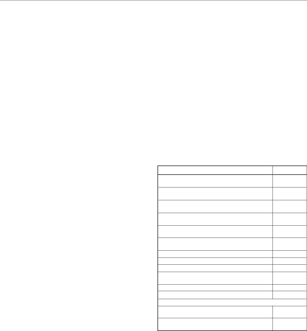
Flue Terminal Positions
Min. Spacing*
1. Directly below, above or alongside an opening
window, air vent or other ventilation opening. 300mm (12")
2. Below guttering, drain pipes or soil pipes. 25mm ( 1")*
BS5440-1 2000 75mm (3")
3. Below eaves. 25mm (1")*
BS5440-1 2000 200mm (8")
4. Below balconies or a car port roof. 25mm (1")*
BS5440-1 2000 200mm (8")
5. From vertical drain pipes or soil pipes. 25mm (1")*
BS5440-1 2000 150mm (6")
6. From an internal or external corner or to a 25mm (1")*
boundary along side the terminal. BS5440-1 2000 300mm (12")
7. Above adjacent ground, roof or balcony level. 300mm (12")
8. From a surface or a boundary facing the terminal. 600mm (24")
9. From a terminal facing a terminal. 1,200mm (48")
10. From an opening in a car port
(e.g. door or window) into dwelling. 1,200mm (48")
11. Vertically from a terminal on the same wall. 1,500mm (60")
12. Horizontally from a terminal on the wall. 300mm (12")
Vertical Terminals
13. Above the roof pitch with roof slope of all angles. 300mm (12")
Above flat roof. 300mm (12")
14. From a single wall face. 600mm (24")
From corner walls. 1000mm (40")
Table 3 - Balanced Flue Terminal Position
* Only one reduction down to 25mm is allowable per installation
otherwise BS5440-1 2000 dimensions must be followed.