


20
icos - Installation & Servicing
INSTALLATION
23
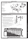
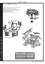
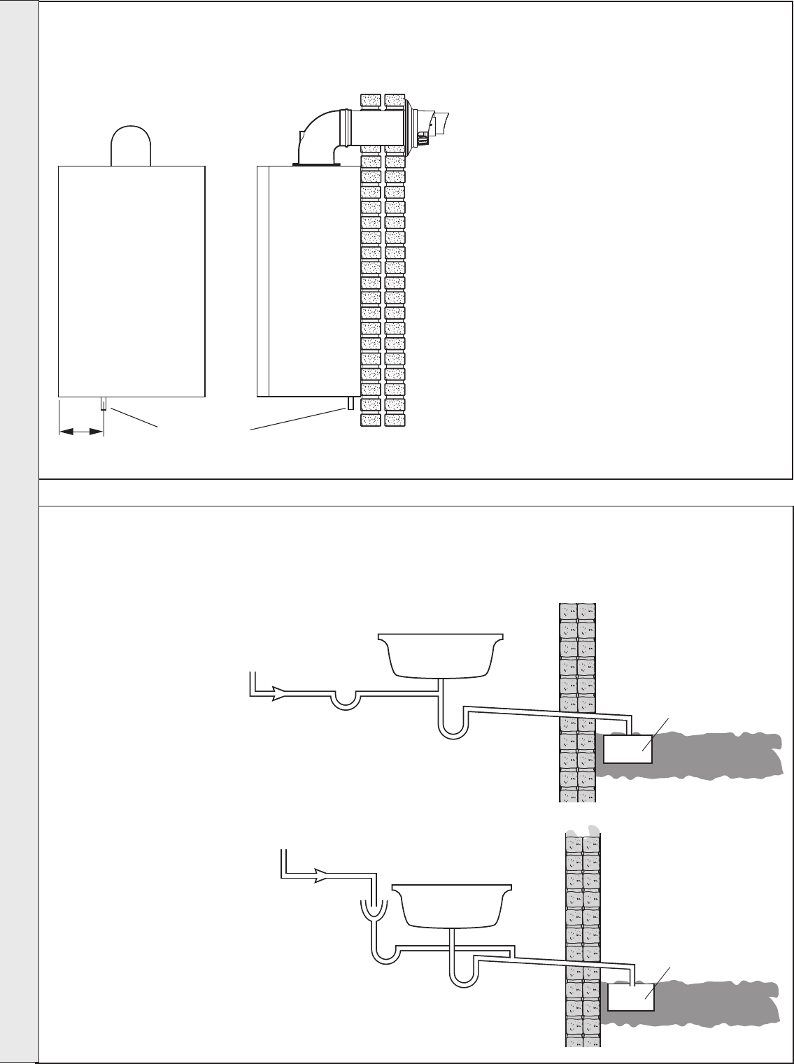
CONDENSATE DRAIN
The condensate drain provided on the boiler must be
connected to a drainage point, preferably within the
building.
Ensure that the condensate trap is full of water
before commissioning the boiler. Refer to Frame 27.
The routing of the drain must be made to allow a
minimum fall of 1 in 20 away from the boiler,
throughout its length.
The drainage pipework must be arranged so that
obstruction (e.g. through freezing) of external
drainage pipe does not give rise to spillage within
the dwelling.
IMPORTANT. If excessive external pipework cannot
be avoided an additional siphon kit and insulation
are recommended, in order to prevent possible
freezing.
All pipework and fittings in the condensate drain
system must be made of plastic. No other materials
may be used.
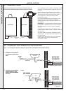
The drain outlet on the boiler is standard 21.5mm
overflow pipe. This size must not be reduced in any
part of its length.
A plastic cap is fitted to the end of the condensate
drain adapter this must be removed before
connection is made.
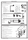
nm8734
Front View Side View
155mm
Condensate
drain
Refer also to the British Gas document: 'Guidance Notes for
the Installation of Domestic Gas Condensing Boilers' (1989).
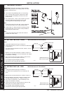
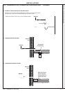
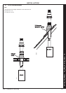
BOILER
cla7771
75mm trap
Sink constitutes
air break
DRAIN
Ground Level
Open end of pipe
direct into gulley
below grating but
above water level
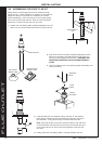
cla9252
75mm trap
DRAIN
Sink
Ground Level
Open end of pipe
direct into gulley
below grating but
above water level
BOILER
Air Break
1. INTERNAL TO SINK WASTE
UPSTREAM OF SINK WASTE
TRAP
2. INTERNAL TO SINK WASTE
DOWNSTREAM OF SINK
WASTE TRAP (PREFERRED
METHOD)
Note. ALL EXTERNAL PIPE RUNS MUST BE INSULATED - MAXIMUM LENGTH 3M EXTERNAL
24
CONDENSATE PIPE TERMINATION CONFIGURATIONS
continued . . . .
INSTALLATION