


17
icos - Installation & Servicing
INSTALLATION
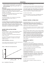
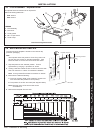
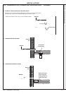
FLUE OUTLET
1
nm8752
16
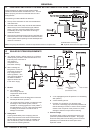
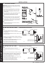
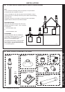
WALL MOUNTING TEMPLATE
15
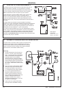
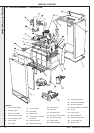
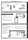
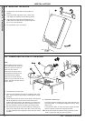
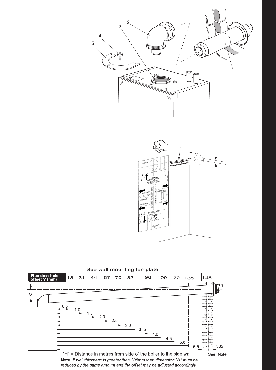
FLUE ASSEMBLY - Exploded View
LEGEND
1. Duct assembly.
2. Flue turret.
3. Turret gasket.
4. M5 x 10 pozi screw.
5. Turret clamp.
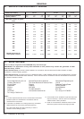
An optional flue duct extension kit is required for
wall thicknesses greater than :
Side 395mm
Rear 435mm
nm9283
V - See Diagram Below
Extended centre line
155
Rear flue arrangement shown
nm8731
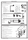
The wall mounting template is located on the internal top
protective packaging.
Note.
The template shows the positions of the fixing holes and
the rear flue hole centre for standard installation. Care
MUST be taken to ensure the correct holes are drilled.
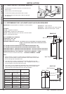
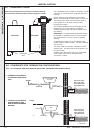
1. Tape template into the selected position. Ensure
squareness by hanging a plumbline as shown.
2. If fitting a side flue extend the flue centre line onto the side
wall and measure in 155mm for standard installation.
Note. If using stand-off kit distance increases to 188mm.
3. Mark onto the wall the following:
a The wall mounting plate screw positions (choose one
from each side with preference to top holes).
b. The position of the flue duct hole (see diagram below).
Note. Mark the centre of the hole as well as the
circumference.
4. Remove the template from the wall.