


15
icos - Installation & Servicing
INSTALLATION
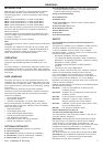
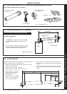
G
C
A
B
E
F
D
nm7890
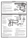
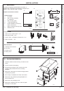
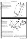
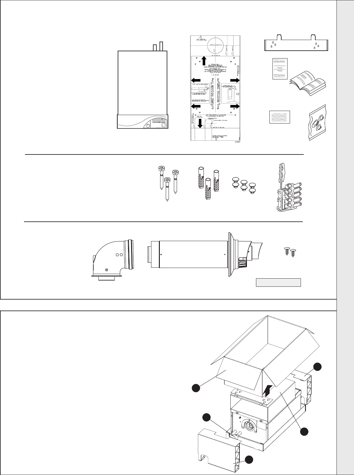
The boiler is supplied fully assembled in one Pack A,
together with a telescopic flue assembly for lengths up to
595mm, rear or side flue outlet, in Pack B.
Unpack and check the contents.
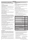
11
UNPACKING
Hardware Pack
A 50mm x No.14 wood screws - 3 off
B Wall plugs (TP2B ) - 3 off
C Push-in caps - 6 off (Refer to Frame 36 no. 15)
D Mains connector - 1 off
Pack A Contents
A The boiler
B Wall mounting template
on cardboard
C Wall mounting plate
D 1 year guarantee form
E These Installation & Servicing/
User’s Instructions
F Water Treatment Warning Label
G Hardware pack
B Pack Contents
A Telescopic flue terminal
B Flue turret
C Screws (2 off)
D Sealing Tape
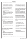
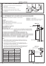
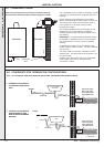
1. Ensure the boiler is stood correctly, as marked on the
carton.
2. Cut and remove the strapping.
3. Fold back the top flaps to gain access to the wall
mounting plate, literature and wall mounting
template.
4. Remove the instructions and read thoroughly before
unpacking the product.
5. When ready for installation lift off the outer sleeve.
6. Remove the top protection packing/template and
save for further use.
7. Remove the two packaging ends.
8. Remove the hardware pack from under the pipes
and keep in a safe place.
12
PACKAGING REMOVAL
3
8
6
7
7
5
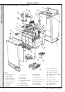
nm9282
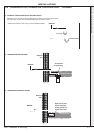
C
nm8465
D
A
B
nm8751
A
B
C
D
INSTALLATION