


12
icos - Installation & Servicing
GENERAL
7
SEALED SYSTEM REQUIREMENTS - continued
pressure. The cold feed pipe from the cistern should
include a non-return valve and a stop valve with an
automatic air vent connected between them, the stop
valve being located between the system and the
automatic air vent. The stop valve may remain open
during normal operation of the system if automatic
water make-up is required.
b. Through a self-contained unit comprising a cistern,
pressure booster pump (if required) and, if necessary,
an automatic pressure reducing valve and flow
restrictor. The cistern should be supplied through a
temporary connection from a service pipe or cold
water distributing pipe.
This unit may remain permanently connected to the
heating system to provide limited automatic water
make-up. Where the temporary connection is supplied
from a service pipe or distributing pipe which also
supplies other draw-off points at a lower level then a
double check valve shall be installed upstream of the
draw-off point.
c. Through a temporary hose connection from a draw-off
tap supplied from a service pipe under mains
pressure. Where the mains pressure is excessive a
pressure reducing valve shall be used to facilitate
filling.
The following fittings shall form a permanent part of
the system and shall be fitted in the order stated:
A stop valve complying with the requirements of
BS. 1010, Part 2 (the hose from the draw-off tap shall
be connected to this fitting).
A test cock.
A double check valve of an approved type.
• Thoroughly flush out the whole of the system with
cold water, without the pump in position.
• With the pump fitted, fill and vent the system until the
pressure gauge registers 1.5 bar (21.5lb/in
2
).
Examine for leaks.
• Check the operation of the safety valve by manually
raising the water pressure until the valve lifts. This
should occur within ± 0.3 bar (± 4.3lb/in
2.
) of the
preset lift pressure.
• Release water from the system until the initial system
design pressure is reached.
• Light the boiler and heat the system to the maximum
working temperature. Examine for leaks.
• Turn off the boiler and drain the system while still hot.
• Refill and vent the system.
• Adjust the initial pressure to the required value.
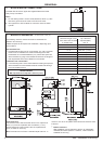
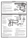
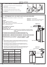
4. Expansion Vessel
a. A diaphragm type expansion vessel must be
connected to a point close to the inlet side of the
pump, the connecting pipe being not less than 15 mm
(
1/2" nominal) size and not incorporating valves of
any sort.
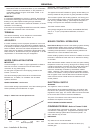
b. The vessel capacity must be adequate to accept the
expansion of the system water when heated to
110
o
C (230
o
F).
c. The charge pressure must not be less than the
static water head above the vessel. The pressure
attained in the system when heated to 110
o
C (230
o
F) should be at least 0.35 bar (5 Ib/in
2
) less than the
lift pressure of the safety valve.
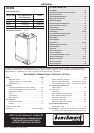
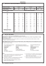
For guidance on vessel sizing refer to the table in
Frame 8.
For further details refer to BS. 5449, BS. 7074:1 and
the British Gas Corporation publication 'Material and
Installation Specifications for Domestic Central
Heating and Hot Water'. For IE refer to the current
edition of I.S.813.
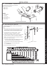
5. Cylinder
The cylinder must be either of the indirect coil type or a
direct cylinder fitted with an immersion calorifier which is
suitable for operating on a gauge pressure of 0.35 bar
(5 Ib/in
2
) in excess of the safety valve setting. Single feed
indirect cylinders are not suitable for sealed systems.
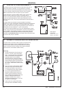
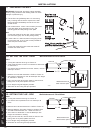
6. Make-up Water
Provision must be made for replacing water loss from the
system, either:
a. From a manually filled make-up vessel with a readily
visible water level. The vessel should be mounted at
least 150 mm (6") above the highest point of the
system, and be connected through a non-return valve
to the system, fitted at least 300 mm (12") below the
make-up vessel on the return side of the domestic
hot water cylinder or radiators.
or
b. Where access to a make-up vessel would be difficult
by pre-pressurisation of the system. Refer to 'Filling',
below.
7. Mains Connection
There must be no direct connection to the mains water
supply or to the water storage tank supplying domestic
water, even through a non-return valve, without the
approval of the local water authority.
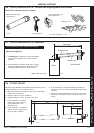
8. Filling
The system may be filled by one of the following
methods:
a. Through a cistern, used for no other purposes, via a
ball valve permanently connected directly to a service
pipe and/or a cold water distributing pipe.
The static head available from the cistern should be
adequate to provide the desired initial system design
Sizing procedure for expansion vessels: The volume of the expansion vessel (litres) fitted to a sealed system shall not be
less than that given by the table on the following page, multiplied by a factor of 0.8 (for flow temperatures of less than 83
o
C).