


43
icos - Installation & Servicing
SERVICING
66
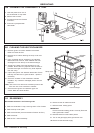
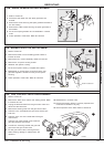
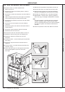
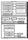
HEAT EXCHANGER REPLACEMENT
Refer also to Frame 10, 'Boiler exploded view'.
1. Refer to Frame 52.
2. Remove front, bottom and sealing panels. Refer to
Frames 45 & 46.
3. Remove the control box and place to one side. Refer to
Frame 61.
4. Attach a length of hose to the drain nipple on the bottom
of the heat exchanger and drain down the boiler.
5. Remove the fan assembly and place to one side. Refer
to Frame 54.
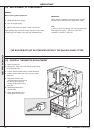
6. Remove the burner and place to one side. Refer to
Frame 48.
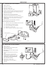
7. Remove the ignition and detection electrodes. Refer to
Frames 56 & 57.
8. Remove the spark generator. Refer to Frame 58.
9. Release the flue from the turret.
10.Remove the turret from the boiler. Refer to Frame 15.
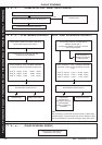
11. Release the silicon tubing from the sample point.
12.Release the electrical connections to the flue
thermistor.
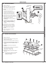
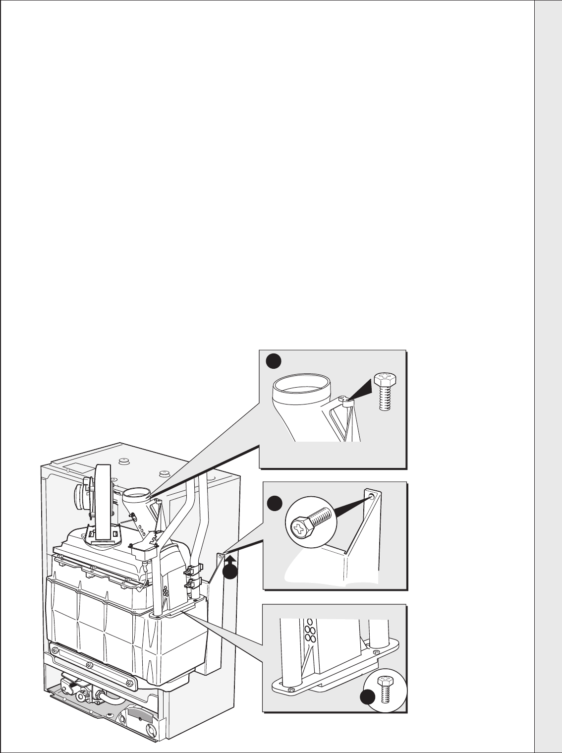
13.Unscrew the M5 x 10 screw retaining the top manifold
flue casing.
14.Remove the top half of the flue manifold from the
appliance.
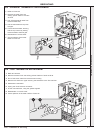
15.Undo the 4 M5 x 10 screws securing the bottom flue
manifold casting.
16.Pull the CH return pipe, CH flow pipe and the bottom
flue manifold together up and out of the heat
exchanger.
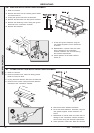
17.Remove the condensate 'S' trap. Refer to Frame 49.
18.Unscrew the 2 M5 x 10 screws from the inter panel.
19.Slide the heat exchanger and inter panel assembly
upwards to disengage and remove from the casing.
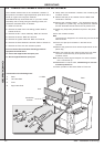
20.Transfer the interpanel to the new heat exchanger.
21.Reassemble in reverse order, replacing gaskets or
seals if any sign of damage or deterioration is evident.
Note.
The heat exchanger is supplied with new combustion
chamber insulation boards. These should be fitted
(refer to Frame 65) before the burner and fan assembly
and before the ignition and detection electrodes are
replaced.
25.Check the operation of the boiler. Refer to Frame 52.
nm8749
13
18
19
15
SERVICING