


31
icos - Installation & Servicing
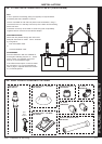
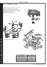
INSTALLATION
nm8780
41
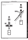
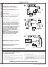
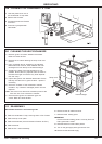
INITIAL LIGHTING
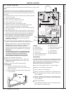
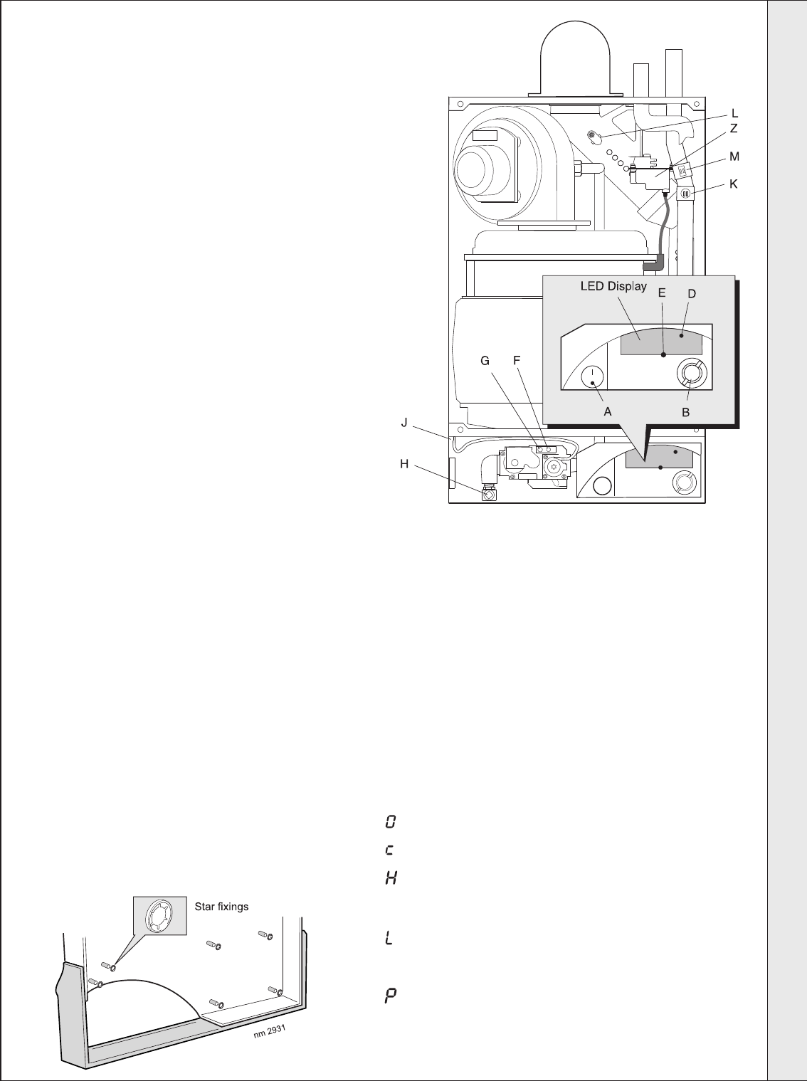
LEGEND
A On/Off switch.
B Thermostat knob.
D 'Burner On' neon.
E Reset button.
F Injector pressure test point.
G Inlet pressure test point.
H Gas service cock.
J Casing pressure test point.
K Overheat thermostat.
L Flue thermistor.
M Flow thermistor.
Z Spark generator.
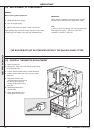
Note.
It is important the burner is not operated before the system is fully
vented of air. If it is necessary to operate the appliance pump to
assist venting of the air this must be done with the gas service cock
turned off.
2. Check that all drain cocks are closed and any valves in the flow
and return are open.
3. Check the electrical supply is off.
4. Ensure the boiler sealing panel is fitted.
5. Check the gas service cock is open.
6. Check that the boiler on/off switch (A) is OFF
7. Slacken the screw in the inlet pressure test point (G) and
connect a gas pressure gauge via a flexible tube.
8. Switch the electricity supply ON and check all external controls
are calling for heat.
9. Set the boiler thermostat knob (B) to position 6 and switch the
boiler on/off switch (A) to ON. The boiler control should now go
through its ignition sequence until the burner is established.
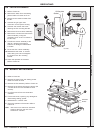
10.If the boiler does not light after 3 attempts the fault codes
L' 'F'
will be displayed. Press the reset button (E); the boiler will
then repeat its ignition sequence. When the burner is
established the WHITE burner ON neon (D) will be
permanently illuminated
11. Ensure that with the boiler operating the dynamic gas
pressure is able to obtain maximum output. Refer to Table 2.
1. Check that the system has been filled and that the boiler is not air locked.
N.B. The principle of the 1:1 gas valve ensures that the
icos HE range is able to deliver it’s full output at inlet
pressures down to 14mb. However if dynamic
pressures below 20mb are experienced ensure this is
adequate for ALL other gas appliances in the property.
IMPORTANT.
The gas input to the burner is regulated by the gas
valve according to the air flow produced by the fan.
It is NOT user-adjustable. Any interference to
sealed settings on the gas valve will adversely
affect operation and render our warranty void.
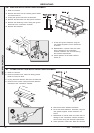
12.Switch OFF the boiler on/off switch.
13.Remove the pressure gauge and tube. Tighten the
sealing screw in pressure test point. Ensure a gas
tight seal is made.
14.Refit the boiler front panel and bottom panel.
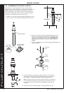
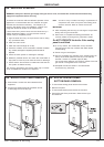
15. THE FASCIA
a. To remove the plastic fascia, prise off the
retaining star washers using a pair of pliers and
place to one side.
b. Fill the remaining fixing holes with the white push
in caps provided.
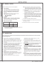
THE DISPLAY
The user control has one neon and one display to inform the
user about the status: the display will show the status of the
boiler and the neon will show the status of the flame. If no
flame is detected the neon is blinking. When the flame is
detected the neon will be lit permanently.
Below is a list with display function in normal operation.
Standby. No demand for heat present.
Boiler is active for central heating.
Boiler is in lockout for a specific error. The display will be
blinking, alternating with a number or letter to show which
error is detected.
Boiler is in lockout for a specific error. The display will be
blinking, alternating with a number or letter to show which
error is detected.
Boiler frost protection
Note: Boiler frost protection occurs at a temperature less
than 3 degrees. The boiler will fire.
INSTALLATION