


11
icos - Installation & Servicing
GENERAL
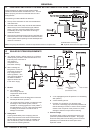
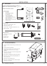
Non-return
valve
Automatic
air vent
Hose unions
Additional
stop valve
Hose connector
Hosepipe
(disconnect
after filling)
Double check valve
assembly
(note direction of flow)
Temporary hose
(disconnect
after filling)
ecl6060
Note. The pump manufacturers' minimum requirements must be complied with.
5
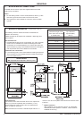
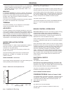
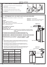
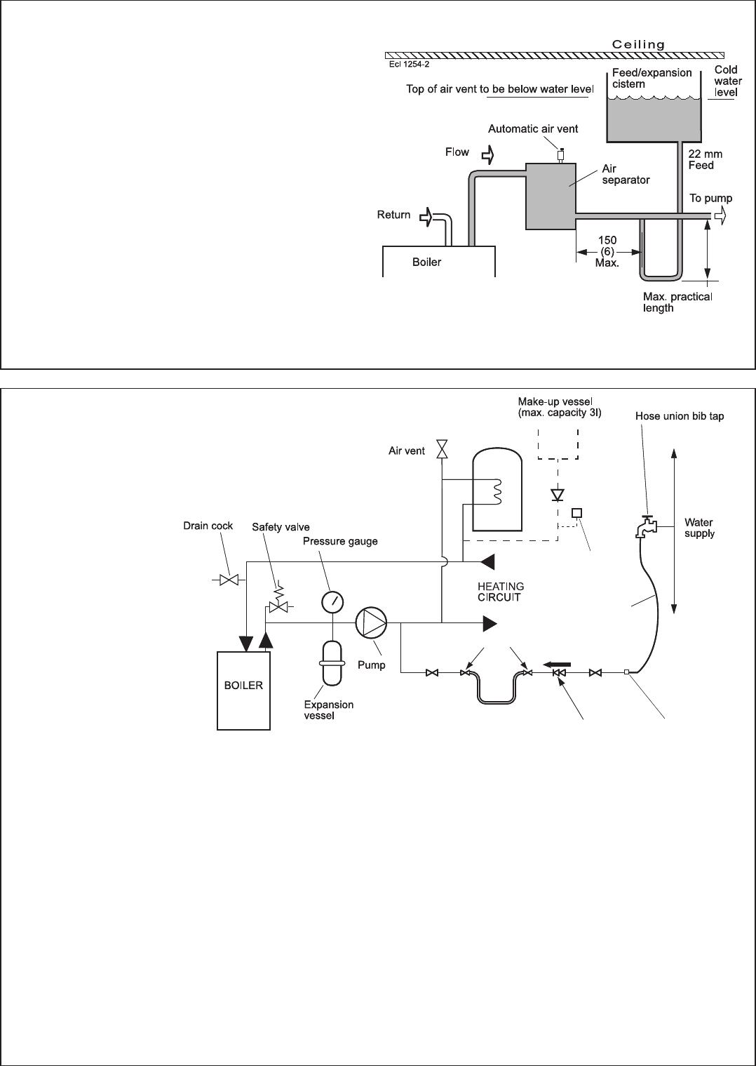
LOW HEAD AND LARGE SYSTEMS WITH EXTENSIVE PIPE RUNS - OPEN VENT
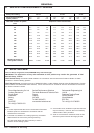
All dimensions in mm (in.).
NB. Imperial dimensions are approximate
6
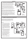
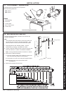
SEALED SYSTEM REQUIREMENTS
This arrangement is useful for large systems where
radiators at the extremities are difficult to vent. This can
lead to pumping over with conventional feed and vent
arrangements.
The following conditions MUST be observed:
1. The top of the automatic air vent must be below the
cold water level.
2. The static water level (cold) must be at least 200mm
above the top of the horizontal flow pipe, fitted as
shown. The vent connection MUST NOT be made
immediately off the top of the boiler as venting is
made less efficient.
3. The maximum practical length of 22mm cold feed pipe
should be used in order to reduce the effective volume
of hot system water expanding into the feed/expansion
cistern to a minimum.
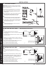
a. A non-adjustable preset lift pressure not exceeding
3bar (45lb/in
2
).
b. A manual testing device.
c. Provision for connection of a discharge pipe.
The valve or discharge pipe should be positioned so
that the discharge of water or steam cannot create a
hazard to the occupants of the premises or cause
damage to electrical components and wiring.
3. Pressure Gauge
A pressure gauge covering at least the range 0-4 bar
(0-60 lb/in
2
) must be fitted to the system. The gauge
should be easily seen from the filling point and should
preferably be connected at the same point as the
expansion vessel.
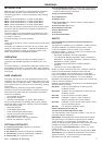
Notes.
a. The method of filling, refilling, topping up or flushing
sealed primary hot water circuit from the mains via a
temporary hose connection is
only allowed if
acceptable to the
local water authority.
b. When installing the
filling device, it must be
connected as shown to
fully comply with the
water regulations. This
may involve the fitting of
an additional WRAS
approval isolator valve
to the mains supply.
1. General
a. The installation
must comply with the
requirements of BS. 6798
and BS. 5449.
b. The installation should be designed to work with
flow temperatures of up to 82
o
C.
c. All components of the system, including the heat
exchanger of the indirect cylinder, must be
suitable for a working pressure of 3 bar (45lb/in
2
)
and temperature of 110
o
C. Care should be taken
in making all connections so that the risk of
leakage is minimised.
2. Safety Valve
A spring loaded safety valve complying with the
relevant requirements of BS. 6759 must be fitted in
the flow pipe as close to the boiler as possible and
with no intervening valve or restriction. The valve
should have the following features: