


ZIO
®
/ZIO PLUS LCD WALL MODULES
5 63-2719—03
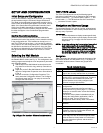
General Settings
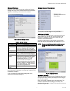
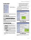
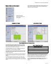
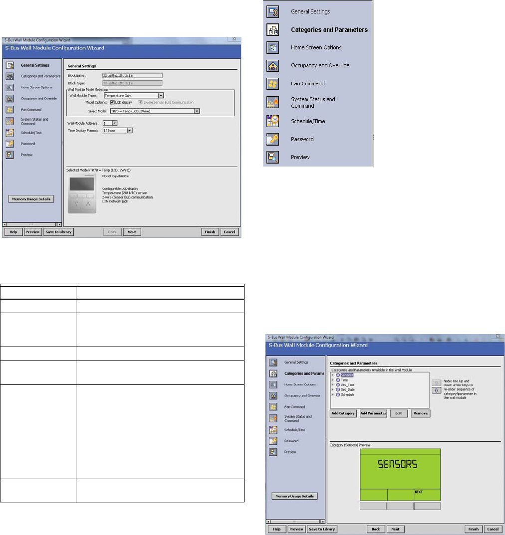
Using Fig. 6 and Table 4 as a guide, configure the General
Settings. An image of the selected model and its capabilities
updates in the display at the bottom of the window.
Fig. 6. General Settings screen.
If you are creating a customized configuration or modifying a
pre-programmed configuration, continue with “Categories and
Parameters” on page 5.
If you are using a pre-programmed configuration as is,
continue with “Preview” on page 17.
Categories and Parameters
I Categories and
Parameters selection from
Wizard Menu
The categories and parameters menu item allows you to
create, edit, and delete categories and parameters.
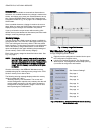
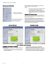
ADDING A CATEGORY
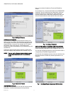
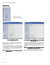
Fig. 7 shows the categories listed in tree format in the main
window where you can add, edit, or remove them. In the
bottom pane, Category Preview (at the bottom of Fig. 7)
shows the current selected item.
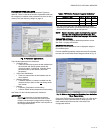
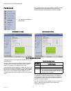
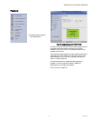
Clicking the Add Category button displays a details pane
below the category and parameter tree as shown in Fig. 8.
NOTE: You can use the Remove button to delete unused
categories and parameters to free up memory
space.
Fig. 7. Category Preview.
CATEGORY DETAILS
When you select a category from the Categories tree list and
click the Edit button, a details pane displays for that category
(see Fig. 8 on page 6).
Here you can enter a category name and description. The
number of parameters in this category are shown. The
description text you enter is loaded to the controller but cannot
be seen in the preview.
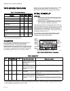
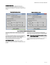
Table 4. General Settings.
Item Function/Use
Block Name The wizard displays S-Bus Wall Module.
Wall Module
Type
Select the appropriate type (Temperature
Only, or a combination of Temperature,
and/or Humidity) from the drop down list.
Model Options Click LCD Display.
Select Model Select the appropriate model, TR70,
TR71, or TR75, from the drop down list.
Wall Module
Address
Select a unique address for each TR70
Series devices connected to the Spyder.
TR70 can be set from 1-5 and TR71/
TR75s can be set from 1-10. The
address selected must match the
address setting at the wall module (using
the rotary switches). If setting the TR71/
TR75 rotary switch to 0, set the address
to 10 in the configuration tool.
Time Display
Format
Select 12 or 24 hour format.