OPERATING GUIDE
63-2719-03
Zio
®
/Zio Plus LCD Wall Modules
TR70, TR71, TR75 with Sylk
®
Bus
APPLICATION
The Zio TR70 Series (TR70, TR70-H, TR71, TR71-H, TR75,
and TR75-H OS numbers) LCD Wall Modules provide an
operator interface for monitoring and adjusting parameters in
the wall module itself and in the programmable controller
(refer to the
Honeywell Spyder
®
User’s Guide,
form 63-2662,
or the
ComfortPoint™ Programmable Controller User’s Guide,
form 63-2663, depending on the programmable controller
used) to which it is wired. The wall module may be customized
and supports both a contractor and a tenant user interface.
NOTE: This document illustrates the wall module configura-
tion process using information from the
Honeywell
Spyder User’s Guide
(form 63-2662).
The wall module has a snap in mounting to a subbase that
may be mounted on a wall, on a standard utility conduit box, or
on a 60 mm wall outlet box. Wiring connections to the wall
module are made through a cutout in the back of the wall
module.
All models have a space temperature sensor, network bus
jack, and an LCD panel with three softkeys and two Up/Down
adjustment keys. Models with -H also include an onboard
humidity sensor.
PREFACE
This Operating Guide is intended to provide configuration
information (using the Niagara Workbench tool) and a general
overview of the TR70 Series operator interface. Configuration
begins with “Initial Power-Up” on page 2, and the general
overview begins with “Operating the Zio Wall Module” on
page 19.
It is intended to guide you through the features and operation
of the TR70 Series as you interface with the programmable
controller and establish pre-programmed or custom
configurations.
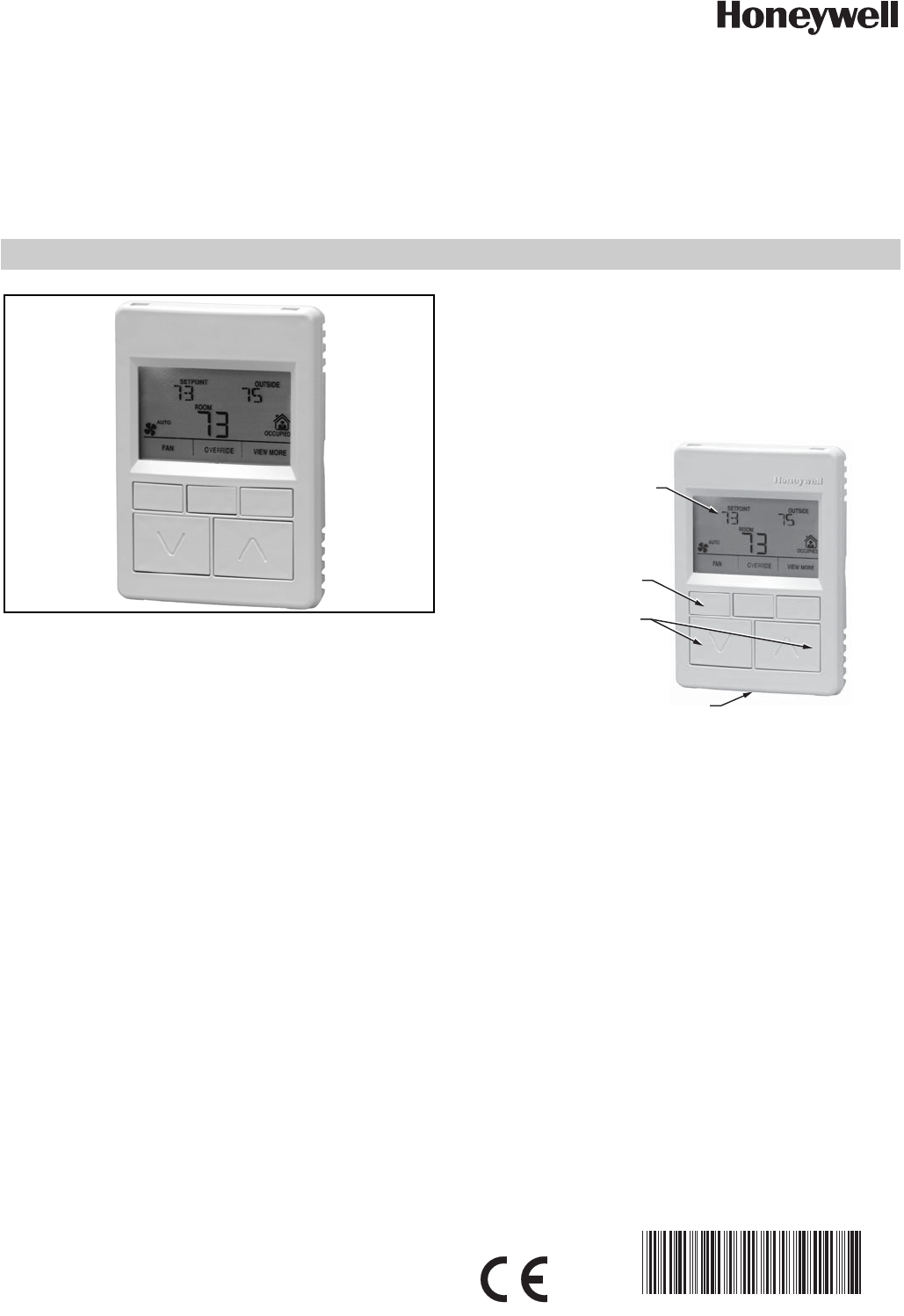
Fig. 1. LCD Wall Module features.
Contents
Application ........................................................................ 1
Preface ............................................................................. 1
TR70 Series Features ....................................................... 2
Compatibility ............................................................. 2
Initial Power-Up ................................................................. 2
Setup and Configuration ................................................... 3
Initial Setup and Configuration .................................. 3
Selecting the Wall Module ......................................... 3
TR71/TR75 Labels .................................................... 3
Navigation and Memory Usage ................................. 3
Wall Module Configuration ........................................ 4
General Settings ................................................... 5
Categories and Parameters .................................. 5
Home Screen Options ........................................... 9
Occupancy and Override ...................................... 10
Fan Command ....................................................... 12
System Status and Command .............................. 13
Schedule/Time ...................................................... 14
Password ............................................................... 15
Preview .................................................................. 16
Completing the Setup and Configuration .................. 17
Operating the Zio Wall Module ......................................... 19
Contractor Mode Operation ...................................... 19
Tenant Mode Operation ............................................ 22
LCD PANEL
M27344
SOFTKEYS (3)
UP/DOWN
ARROW KEYS
NETWORK BUS PORT (ON BOTTOM OF CASE)


