


Installation
311879F 7
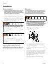
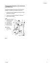
Mountings
• Be sure the mounting surface can support the
weight of the pump, hoses, and accessories, as well
as the stress caused during operation.
• For all mountings, be sure the pump is bolted
directly to the mounting surface.
• For ease of operation and service, mount the pump
so the air valve cover (2), air inlet, and fluid inlet and
outlet ports are easily accessible.
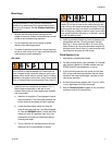
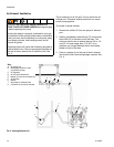
Air Line
1. Install the air line accessories as shown in FIG. 2.
Mount these accessories on the wall or on a
bracket. Be sure the air line supplying the accesso-
ries is grounded.
a. Install an air regulator (C) and gauge to control
the fluid pressure. The fluid outlet pressure will
be the same as the setting of the air regulator.
b. Locate one bleed-type master air valve (B)
close to the pump and use it to relieve trapped
air. See the WARNING above. Locate the other
master air valve (E) upstream from all air line
accessories and use it to isolate them during
cleaning and repair.
c. The air line filter (F) removes harmful dirt and
moisture from the compressed air supply.
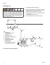
2. Install a grounded, flexible air hose (A) between the
accessories and the 1/2 npt(f) pump air inlet (N).
See Fig. 5. Use a minimum 3/8 in. (9.5 mm) ID air
hose. Screw an air line quick disconnect coupler (D)
onto the end of the air hose (A), and screw the mat-
ing fitting into the pump air inlet snugly.
Fluid Suction Line
1. Use flexible, grounded fluid hoses.
2. For best sealing results, use a standard Tri-Clamp®
style sanitary gasket of a flexible material such as
EPDM, Buna-N, fluoroelastomer, or silicon.
3. If the fluid inlet pressure to the pump is more than
25% of the outlet working pressure, the ball check
valves will not close fast enough, resulting in ineffi-
cient pump operation.
4. At inlet fluid pressures greater than 15 psi (0.1 MPa,
1 bar), diaphragm life will be shortened.
5. See the Technical Data on pages 32, 40, and 48 for
maximum suction lift (wet and dry).
CAUTION
The pump exhaust air may contain contaminants.
Ventilate to a remote area if the contaminants could
affect your fluid supply. See Air Exhaust Ventilation
on page 10.
A bleed-type master air valve (B) is required in the sys-
tem to relieve air trapped between this valve and the
pump. Trapped air can cause the pump to cycle unex-
pectedly, which could result in serious injury, including
splashing in the eyes or on the skin, injury from moving
parts, or contamination from hazardous fluids. See F
IG.
2.
In the step below, do not connect the quick-disconnect
coupler (D) on the air hose to the mating fitting on the
pump until you are ready to operate the pump. Connect-
ing the coupler too early can result in unintentional oper-
ation of the pump, leading to serious injury from moving
parts, splashing fluid in the eyes or on the skin, and con-
tact with hazardous fluids.