


Service
24 311879F
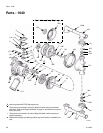
Bearing and Air Gasket Removal
Tools Required
• Torque wrench
• 10 mm socket wrench
• Bearing puller
• O-ring pick
• Press, or block and mallet
Disassembly
1. Relieve the pressure.
2. Remove the manifolds and disassemble the ball
check valves as explained on page 18.
3. Remove the fluid covers and diaphragm assemblies
as explained on page 19.
4. Disassemble the air valve as explained on page 16.
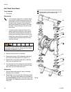
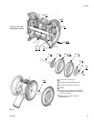
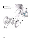
5. Using a 10 mm socket wrench, remove the screws
(25) holding the air covers (23) to the center housing
(1). See F
IG. 14.
6. Remove the air cover gaskets (22). Always replace
the gaskets with new ones.
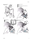
7. Use a bearing puller to remove the diaphragm shaft
bearings (19), air valve bearings (12) or pilot pin
bearings (15). Do not remove undamaged bearings.
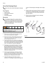
8. If you removed the diaphragm shaft bearings (19)
reach into the center housing (1) with an o-ring pick
and hook the u-cup packings (402), then pull them
out of the housing. Inspect the packings. See F
IG.
11.
Reassembly
1. If removed, install the shaft u-cup packings (402*)
so the lips face out of the housing (1). See F
IG. 11.
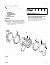
2. The bearings (12, 15, and 19) are tapered and can
only be installed one way. Insert the bearings into
the center housing (1), tapered end first. Using a
press or a block and rubber mallet, press-fit the
bearing so it is flush with the surface of the center
housing.
3. Reassemble the air valve as explained on page 16.
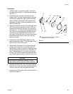
4. Align the new air cover gasket (22) so the pilot pin
(16) protruding from the center housing (1) fits
through the proper hole (H) in the gasket.
5. Align the air cover (23) so the pilot pin (16) fits in the
middle hole (M) of the three small holes near the
center of the cover. Install the screws (25),
handtight. Apply medium-strength (blue) Loctite
® or
equivalent to the threads of the screws (25). See
F
IG. 14. Using a 10 mm socket wrench, torque the
screws oppositely and evenly to 130-150 in-lb
(15-17 N
•m).
6. Install the diaphragm assemblies and fluid covers as
explained on page 19.
7. Reassemble the ball check valves and manifolds as
explained on page 18.
Do not remove undamaged bearings.
To reduce the risk of serious injury, whenever you are
instructed to relieve pressure, always follow the Pres-
sure Relief Procedure on page 11.
If you are removing only the diaphragm shaft
bearing (19), skip step 4.