


Service
311879F 23
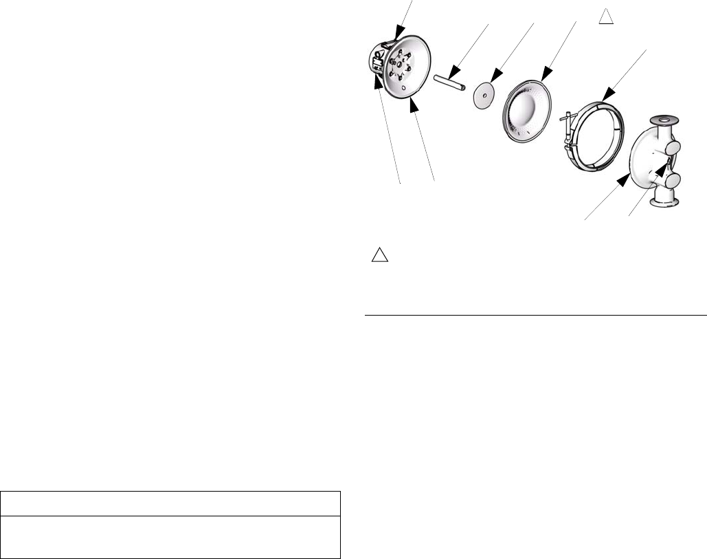
Reassembly
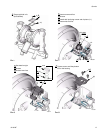
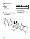
1. Install the shaft u-cup packings (402*) so the lips
face out of the housing (1). Lubricate the packings.
See F
IG. 13.
2. Assemble the air side plate (104) onto the dia-
phragm (403). The wide, radiused side of the plate
must face the diaphragm. Apply medium-strength
(blue) Loctite
® or equivalent to the threads of the
diaphragm assembly. Screw the assembly into the
shaft (24) hand tight.
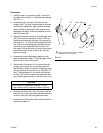
3. Grease the length and ends of the diaphragm shaft
(24). Determine the orientation of the air valve by
checking which side the pilot pins (16) protrude far-
thest (see F
IG. 14). This side will be supplied with air
first. Insert the shaft/diaphragm assembly into this
side of the pump. Assemble the fluid cover (101)
and clamp (106) so the arrow (A) on the cover faces
the same direction as the air valve (B). Securely
tighten the clamp.
4. Assemble the other diaphragm assembly to the
shaft as explained in step 2. This diaphragm will be
lifted off the air cover at this point.
5. Set the other fluid cover (101) in place on the dia-
phragm, so the arrow (A) on the cover faces the
same direction as the air valve (B). Supply the pump
with low pressure air (less than 7 psi [.05 MPa, 0.5
bar]). The diaphragm will very slowly pull onto the
air cover (23). You can support the movement with
your hand by gently pushing on the fluid cover (101).
6. Assemble the fluid cover (101) and clamp (106) so
the arrow (A) on the cover faces the same direction
as the air valve (B). Securely tighten the clamp.
7. Reassemble the ball check valves and manifolds as
explained on page 18.
CAUTION
Do not deform the diaphragm manually. The dia-
phragm needs uniform pressure to deform properly.
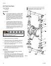
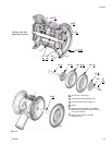
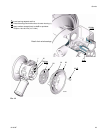
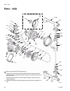
FIG. 13
ti10631a
106
24 104 403*
101
231
Apply medium strength (blue) Loctite® or
equivalent to bolt (not shown).
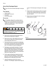
5
5
B
A