


Service
20 311879F
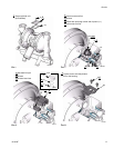
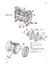
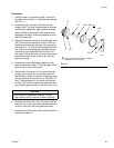
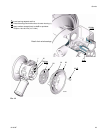
4. Loosen but do not remove the diaphragm shaft bolts
(107), using a 15 mm socket wrench on both bolts.
See F
IG. 11.
5. Unscrew one bolt from the diaphragm shaft (24) and
remove the o-ring (108), fluid side diaphragm plate
(105), diaphragm (403), backer (401) used only on
PTFE models, and air side diaphragm plate (104).
See F
IG. 11.
6. Pull the other diaphragm assembly and the dia-
phragm shaft (24) out of the center housing (1).
Hold the shaft flats with a 19 mm open end wrench,
and remove the bolt (107) from the shaft. Disassem-
ble the remaining diaphragm assembly.
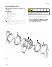
7. Inspect the diaphragm shaft (24) for wear or
scratches. If it is damaged, inspect the bearings (19)
in place. If the bearings are damaged, refer to page
24.
8. Reach into the center housing (1) with an o-ring pick
and hook the u-cup packings (402), then pull them
out of the housing. This can be done with the bear-
ings (19) in place.
9. Clean all parts and inspect for wear or damage.
Replace parts as needed.
Reassembly
1. Install the shaft u-cup packings (402*) so the lips
face out of the housing (1). Lubricate the packings.
See F
IG. 11.
2. Install the diaphragm assembly on one end of the
shaft (24) as follows:
a. Install the o-ring (108*) on the shaft bolt (107).
b. Install the fluid side diaphragm plate (105) on
the bolt so the rounded side faces the dia-
phragm (401).
c. Install the diaphragm (403*). Make certain the
side marked AIR SIDE faces the center
housing (1).
d. On PTFE models only, install the backer (401*)
on the bolt. Make certain the side marked AIR
SIDE faces the center housing (1).
e. Install the air side diaphragm plate (104) so the
rounded side faces the diaphragm (401). This
plate is stamped with its part number.
f. Apply medium-strength (blue) Loctite
® or equiv-
alent to the bolt (107) threads. Screw the bolt
into the shaft (24) hand tight.
3. Grease the length and ends of the diaphragm shaft
(24), and slide it through the housing (1).
4. Assemble the other diaphragm assembly to the
shaft as explained in step 2.
5. Hold one shaft bolt (107) with a wrench and torque
the other bolt to 60-70 ft-lb (81-95 N
•m) at 100 rpm
maximum.
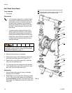
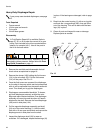
6. Align the fluid covers (101) and the center housing
(1) so the arrows (A) on the covers face the same
direction as the air valve (B). Secure covers with the
clamps. See F
IG. 10.
7. Reassemble the ball check valves and manifolds as
explained on page 18.
The fluid side diaphragm plate (105) is stainless
steel. This plate is not stamped with its part num-
ber. Be sure to install this plate on the fluid side of
the diaphragm.