


Service
18 311879F
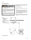
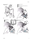
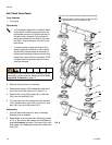
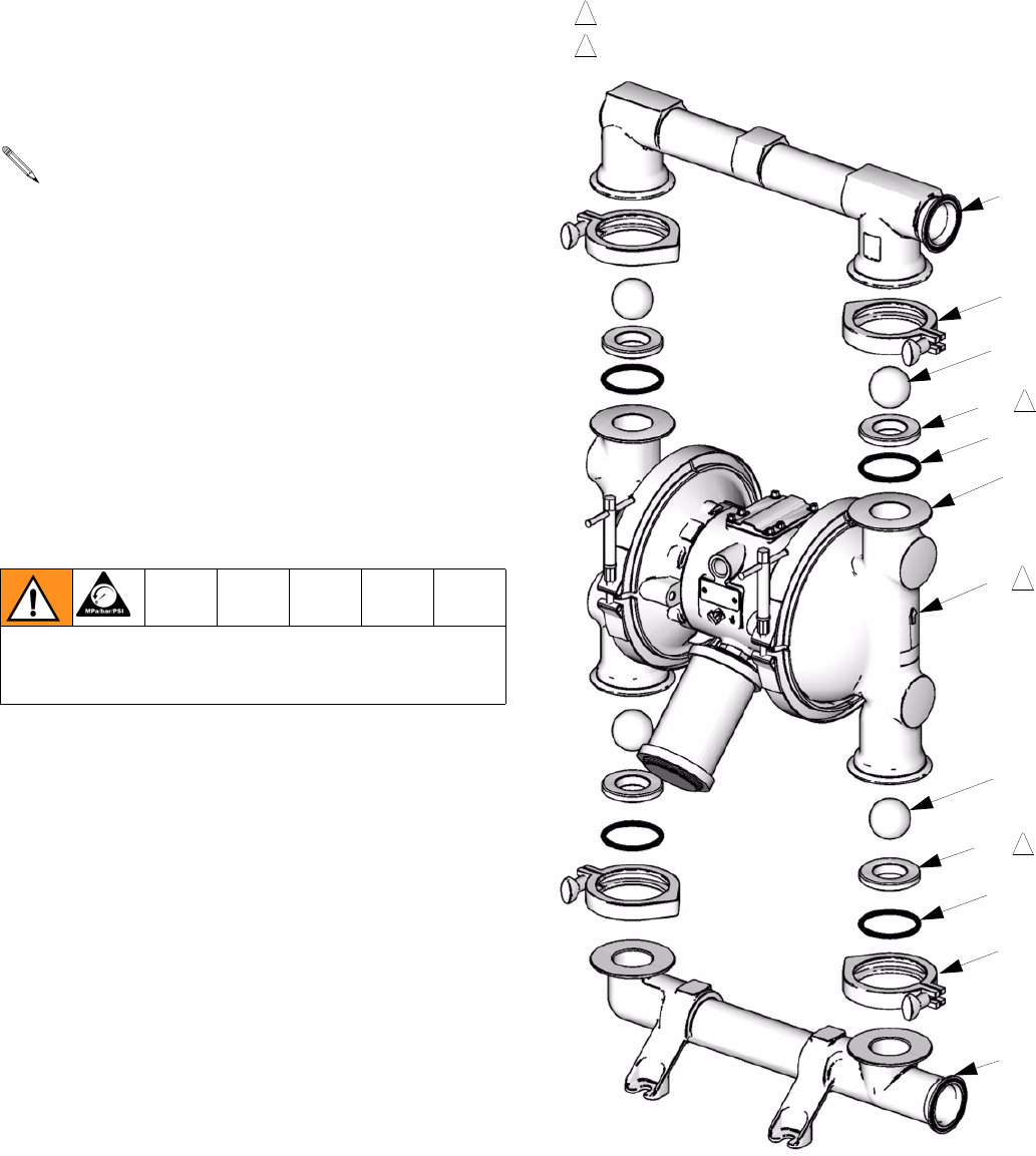
Ball Check Valve Repair
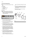
Tools Required
• O-ring pick
Disassembly
1. Relieve the pressure. Disconnect all hoses.
2. Remove the pump from its mounting.
3. Remove the clamps (106) holding the outlet mani-
fold (103) to the fluid covers (101). See F
IG. 9.
4. Remove the o-rings (202), seats (201), and balls
(301) from the manifold (103).
5. Turn the pump over and remove the inlet manifold
(102). Remove the o-rings (202), seats (201), and
balls (301) from the fluid covers (101).
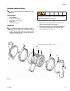
Reassembly
1. Clean all parts and inspect for wear or damage.
Replace parts as needed.
2. Reassemble in the reverse order, following all notes
in F
IG. 9. Be sure the ball checks and manifolds are
assembled exactly as shown. The arrows (A) on the
fluid covers (101) must point toward the outlet man-
ifold (103).
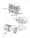
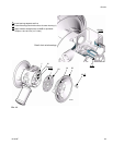
F
IG. 9
• A Fluid Section Repair Kit is available. Refer
to the Repair Kit Matrix parts section for the
appropriate pump size so that the correct kit
for your pump is ordered. Parts included in
the kit are marked with an asterisk, for exam-
ple (202*). Use all the parts in the kit for the
best results.
• To ensure proper seating of the balls (301),
always inspect the seats (201) when replac-
ing the balls. Replace seats as necessary if
seating surface shows evidence of wear. Also,
replace the o-rings (202) as necessary. PTFE
o-rings should be replaced every time mani-
folds are removed.
To reduce the risk of serious injury, whenever you are
instructed to relieve pressure, always follow the Pres-
sure Relief Procedure on page 11.
TI8932a
2
1
Arrow (A) must point toward outlet manifold (103)
Radiused seating surface must face the ball (301).
Large chamfer on O.D. must face o-ring.
103
301*
201
202*
101
A
301*
201
202*
102
1
2
2
113
113