


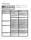

Service
16 311879F
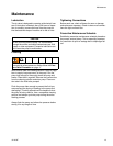
Service
Repairing the Air Valve
Tool Required
• Torque wrench
• Torx (T20) screwdriver or 7 mm (9/32 in.) socket
wrench
• Needle-nose pliers
• O-ring pick
• Lithium base grease
Disassembly
1. Relieve the pressure.
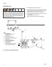
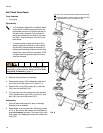
2. With a Torx (T20) screwdriver or 7 mm (9/32 in.)
socket wrench, remove the six screws (3), air valve
cover (2), and gasket (4). See F
IG. 5.
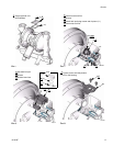
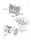
3. Move the valve carriage (5) to the center position
and pull it out of the cavity. Remove the valve block
(7) and o-ring (6) from the carriage. Using a nee-
dle-nose pliers, pull the pilot block (18) straight up
and out of the cavity. See F
IG. 6.
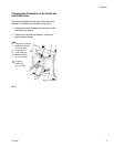
4. Pull the two actuator pistons (11) out of the bearings
(12). Remove the u-cup packings (10) from the pis-
tons. Pull the pilot pins (16) out of the bearings (15).
Remove the o-rings (17) from the pilot pins. See
F
IG. 7.
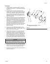
5. Inspect the valve plate (8) in place. If damaged, use
a Torx (T20) screwdriver or 7 mm (9/32 in.) socket
wrench to remove the three screws (3). Remove the
valve plate (8). See F
IG. 8.
6. Inspect the bearings (12, 15) in place. See F
IG. 7.
The bearings are tapered and, if damaged, must be
removed from the outside. This requires disassem-
bly of the fluid section. See page 24.
7. Clean all parts and inspect for wear or damage.
Replace as needed. Reassemble.
Reassembly
1. If you replaced the bearings (12, 15), reinstall as
explained on page 24. Reassemble the fluid section.
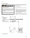
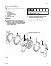
2. Install the valve plate (8) in the cavity, seal down.
Install the three screws (3), using a Torx (T20)
screwdriver or 7 mm (9/32 in.) socket wrench.
Tighten until the screws bottom out on the housing.
See F
IG. 8.
3. Install an o-ring (17†) on each pilot pin (16). Grease
the pins and o-rings. Insert the pins into the bear-
ings (15), narrow end first. See F
IG. 7.
4. Install a u-cup packing (10†) on each actuator pis-
ton (11), so the lips of the packings face the narrow
end of the pistons. See F
IG. 7.
5. Lubricate the u-cup packings (10†) and actuator pis-
tons (11). Insert the actuator pistons in the bearings
(12), wide end first. Leave the narrow end of the pis-
tons exposed. See F
IG. 7.
6. Grease the lower face of the pilot block (18†) and
install so its tabs snap into the grooves on the ends
of the pilot pins (16). See F
IG. 6.
7. Grease the o-ring (6†) and install it in the valve
block (7†). Push the block onto the valve carriage
(5). Grease the lower face of the valve block. See
F
IG. 6.
8. Install the valve carriage (5) so its tabs slip into the
grooves on the narrow end of the actuator pistons
(11). See F
IG. 6.
9. Align the valve gasket (4†) and cover (2) with the six
holes in the center housing (1). Secure with six
screws (3†), using a Torx (T20) screwdriver or 7 mm
(9/32 in.) socket wrench. Torque to 52-60 in-lb
(5.6-6.8 N•m). See F
IG. 5.
Air Valve Repair Kit 255061 is available. Parts
included in the kit are marked with a symbol, for
example (4†). Use all the parts in the kit for the
best results.
To reduce the risk of serious injury, whenever you are
instructed to relieve pressure, always follow the Pres-
sure Relief Procedure on page 11.