


36
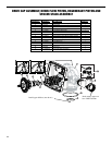
Drive Cap Assembly, Main Piston and Regenerant
Piston
The drive assembly must be removed to access the drive
cap assembly. The drive cap assembly must be removed
to access the piston(s). The drive cap assembly is thread-
ed into the control valve body and seals with an o-ring.
To remove the drive cap assembly use the special plastic
-
bly so it engages the notches molded into the drive back
screwdriver so the drive cap assembly turns counter clock-
wise. Once loosened, unscrew the drive cap assembly by
hand and pull straight out.
The drive cap assembly contains the drive cap, the main
drive gear, drive cap, piston rod and various other parts
replaceable part on the drive cap assembly is the o-ring.
Attached to the drive cap assembly is the main piston and
The regenerant piston (the small diameter one behind the
the side with the number. Chemically clean this in dilute
Reattach the main piston to the drive cap assembly. Reat-
Do not lubricate the piston rod, main piston or regener-
seals. Reinsert the drive cap assembly and piston into
the spacer stack assembly and hand tighten the drive cap
assembly. Continue to tighten the drive cap assembly
using a screwdriver as a ratchet until the black o-ring on
the spacer stack assembly is no longer visible through the
into the drive back plate. Make certain that the main drive
Reattach the drive assembly to the control valve and con-
in. This resets the electronics and establishes the service
service position.
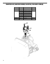
Spacer Stack Assembly
To access the spacer stack assembly remove the drive as-
sembly, drive cap assembly and piston. The spacer stack
assembly can be removed easily without tools by using
necessary. Do not disassemble the stack.
The spacer stack assembly may be chemically cleaned
cloth.
The spacer stack assembly can be pushed in to the
control valve body bore by hand. Since the spacer stack
assembly can be compressed it is easier to use a blunt
the assembly into the control valve body. The assembly
-
sembly in. The control valve body bore interior can be
-
cant on the clear lip seals or the piston.
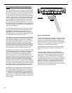
Figure 29