


25
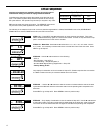
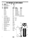
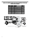
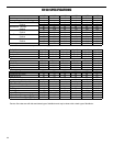
DRIVE CAP ASSEMBLY, DOWN FLOW PISTON, REGENERANT PISTON AND
SPACER STACK ASSEMBLY
1 151-V3004 H150 Drive Cap Assembly 1
2 15-V3135 O-Ring 228 1
4 15-V3174* H150 Regenerant Piston 1
6 151-V3430 H150 Spacer Stack Assy 1
8 151-V3419 O-Ring 347 1
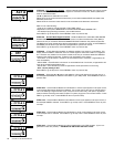
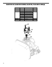
r (located inside meter housing)
1
10 151-V3401-01 H150 Meter Housing 1
11 151-V3223 H150 Meter Clip 1
12 15-V3003** H150 Meter Assy 1
13 15-V3118-01 H150 Turbine Assy 1
14 15-V3105 O-Ring 215 1
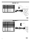
QUANTITY
DRAWING NO.
ORDER NO.
DESCRIPTION
1
2
3
4
5
6
7
15
13
14
12
10
11
8
9
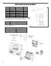
Install upper diffuser (not shown)
Notch marks appear on
hex if BSPT threads.
NPT BSPT
or