


7Heat & Glo • XLR-N-CE, XLR-PB-CE • 2198-900 Rev. J • 5/12
A. ApplianceCertication
NOTINTENDEDFORUSEASAPRIMARYHEATSOURCE.
This appliance is tested and approved as either supplemen-
tal room heat or as a decorative appliance. It should not be
factored as primary heat in residential heating calculations.
C. Non-CombustibleMaterialsSpecication
Material which will not ignite and burn. Such materials are
those consisting entirely of steel, iron, brick, tile, concrete,
slate, glass or plasters, or any combination thereof.
Materials that are reported as passing ASTM E 136,
StandardTestMethodforBehaviorofMaterialsina
Vertical Tube Furnace at 750ºC and UL763 shall be
considered non-combustible materials.
D. CombustibleMaterialsSpecication
Materials made of or surfaced with wood, compressed pa-
per, plant bers, plastics, or other material that can ignite
and burn, whether ame proofed or not, or plastered or
unplastered shall be considered combustible materials.
E. ElectricalCodes
All electrical safety testing has been done following the EN
60335-2-102 standard. Local codes apply.
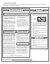
1
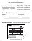
ListingandCodeApprovals
MODELS: XLR-N-CE,XLR-PB-CE
LABORATORY: GLIndustriesLtd.
TYPE: GasFireplace
STANDARD:LatestversionofBSEN613:2001
DIRECTIVE: GAD90/396/EEC
The Heat & Glo gas appliances discussed in this Installer’s
Guide have been tested to certication standards and listed
by the applicable laboratories.
This appliance must be installed in accordance with the
rules in force.
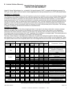
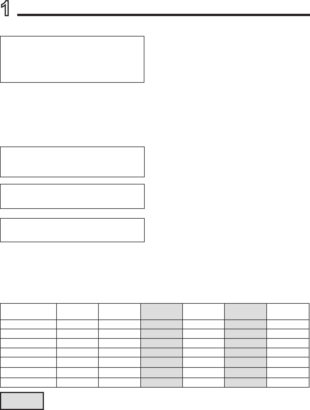
NOX Class 5 for G20, NOX Class 5 for G31
NaturalGas
(G20)
Propane
(G31)
Propane
(G31)
Butane
(G30)
Butane
(G30)
NaturalGas
(G25)
CAT I
2H,
I
2E,
I
2E+
I
3P
I
3P
I
3B/P
I
3B/P
I
2E+
Inlet Pressure 20 mbar 37 mbar 50 mbar 30 mbar 50 mbar 25 mbar
Burner Pressure 8.7 mbar 25 mbar 25 mbar 25 mbar 25 mbar 8.7 mbar
Gas Rate .405
m3
/
h
.134
m3
/
h
.134
m3
/
h
.111
m3
/
h
.111
m3
/
h
.40
m3
/
h
Heat Input (Net) 7.32 kW 6.74 kW 6.74 kW 6.44 kW 6.44 kW 7.32 kW
Burner Injector DMS 42 DMS .057 DMS .057 DMS 55 DMS 55 DMS 42
Pilot Injector 51 30 30 30 30 51
B. GasPressureRequirements
Pressure requirements for XLR replaces are shown in
table below.
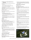
Two taps are provided on the right hand side of the gas
control for a test gauge connection to measure the inlet
and outlet pressures.
Columns highlighted in gray = The gas control valve supplied with this product is approved for a maximum
inlet pressure of 37 mbar. For pressures over 37 mbar, an in line pressure regulator must be installed
upstream from the gas control valve.
A. AdditionalRelatedStandards
The installation must comply with these installation instruc-
tions and all relevant parts of Local and National Building
Standards Regulations and those relevant recommenda-
tions of the following British Standards. BS 5871: Part 1
BS 8303 BS 5440: Parts 1 & 2 BS 6891 BSEN1856 Parts
1 & 2 BS 5482 Part 1, as well as IGE/UP/7.
The replace and its individual shut-off valve must be dis-
connected from the gas supply piping system during any
pressure testing of the system at test pressures in excess
of 60 mbar.
If the replace must be isolated from the gas supply pip-
ing system by closing an individual shut-off valve, it must
be of the handle-less type.