


41Heat & Glo • XLR-N-CE, XLR-PB-CE • 2198-900 Rev. J • 5/12
11
GasInformation
A. GasPressureRequirements
Pressure requirements for XLR-CE replaces are shown
in Table 11.1 below.
Two taps are provided on the right hand side of the gas
control for a test gauge connection to measure the inlet
and outlet pressures.
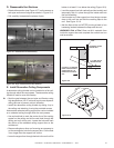
The replace and its individual shut-off valve must be dis-
connected from the gas supply piping system during any
pressure testing of the system at test pressures in excess
of 60 mbar.
If the replace must be isolated from the gas supply pip-
ing system by closing an individual shut-off valve, it must
be of the handle-less type.
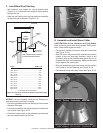
Incoming gas line should be piped into the valve compart-
ment and connected to the ISO 7-Rp 1/2 (BSP Rp 1/2)
threaded gas inlet connection on the manual shutoff valve.
Leak test all gas line points and the gas control valve prior
to and after starting the gas appliance.
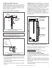
B. GasConnection
Note:Have the gas supply line installed in accordance with
local building codes by a qualied installer approved and/or
licensed as required by the locality.
Note:Before the rst ring of the appliance, the gas supply
line should be purged of any trapped air.
Note:Consult local building regulations to properly size the gas
supply line leading to the (Rp 1/2 in.) hook-up at the unit.
WARNING
CHECK FOR GAS LEAKS
Explosion Risk
Fire Risk
Asphyxiation Risk
• Check all ttings and connections.
• Do not use open ame.
• After the gas line installation is complete, all
connections must be tightened and checked
for leaks with a commercially-available, non-
corrosive leak check solution. Be sure to rinse
off all leak check solution following testing.
Fittings and connections may have loosened
during shipping and handling.
WARNING
Fire Risk
Explosion Risk
High pressure will damage valve.
• Disconnect gas supply piping BEFORE
pressure testing gas line at test pressures
above 60 mbar.
• Close the manual shutoff valve BEFORE
pressure testing gas line at test pressures
equal to or less than 60 mbar.
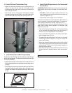
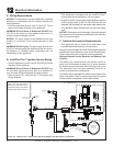
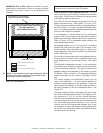
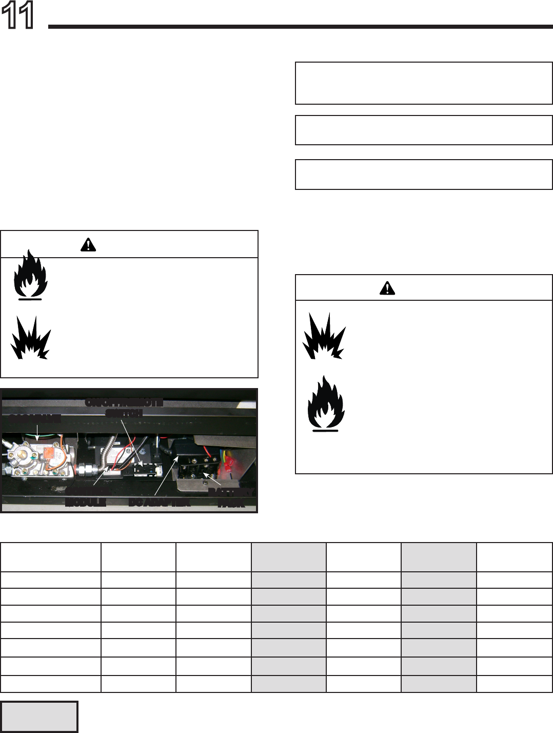
Figure11.1.ValveComponents
NaturalGas
(G20)
Propane
(G31)
Propane
(G31)
Butane
(G30)
Butane
(G30)
NaturalGas
(G25)
CAT I
2H,
I
2E,
I
2E+
I
3P
I
3P
I
3B/P
I
3B/P
I
2E+
Inlet Pressure 20 mbar 37 mbar 50 mbar 30 mbar 50 mbar 25 mbar
Burner Pressure 8.7 mbar 25 mbar 25 mbar 25 mbar 25 mbar 8.7 mbar
Gas Rate .405
m3
/
h
.134
m3
/
h
.134
m3
/
h
.111
m3
/
h
.111
m3
/
h
.40
m3
/
h
Heat Input (Net) 7.32 kW 6.74 kW 6.74 kW 6.44 kW 6.44 kW 7.32 kW
Burner Injector DMS 42 DMS .057 DMS .057 DMS 55 DMS 55 DMS 42
Pilot Injector 51 30 30 30 30 51
Columns highlighted in gray = The gas control valve supplied with this product is approved for a maximum
inlet pressure of 37 mbar. For pressures over 37 mbar, an in line pressure regulator must be installed
upstream from the gas control valve.
GASVALVE
CONTROL
MODULE
ON/OFF/REMOTE
SWITCH
DCADAPTER
BATTERY
PACK
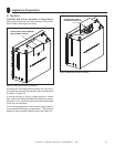
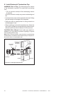
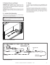
C. AccessThroughtheValveAssembly
Refer to Section 16.C.