


Heat & Glo • XLR-N-CE, XLR-PB-CE • 2198-900 Rev. J • 5/1242
C. OptionalAccessoriesRequirements
• This appliance may be used with a wall switch, wall
mounted thermostat and/or a remote control.
Wiring for optional Hearth & Home Technologies approved
accessories should be done now to avoid reconstruction.
Follow instructions that come with those accessories.
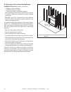
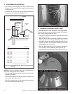
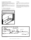
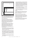
OptionalRemoteControlReceiverandBatteryPack
Location
The battery tray, control module, and remote control re-
ceiver can be accessed through the air space between
the rebox front and the lower-front nishing cover panel.
The decorative front and glass assembly must be re-
moved to access these components.
The battery tray is attached with Velcro to the inside of the
lower cover panel. The IPI control module and the remote
control receiver are placed on the rebox bottom.
12
ElectricalInformation
A. WiringRequirements
NOTICE: This appliance must be installed by a qualied
electrician in accordance with the relevant national and
local regulations.
• Wire the appliance junction cord to 230 VAC. This is
required for proper operation of the appliance.
WARNING! Risk of Shock or Explosion! DO NOT wire
230 VAC to the valve or to the appliance wall switch. In-
correct wiring will damage controls.
NOTICE: The mains supply to the appliance must have
isolation of a minimum 3 mm contact separation in both
poles.
WARNING! Risk of Injury! The gas supply shall be shut
off prior to disconnecting the electrical power and remov-
ing batteries (if installed) before proceeding with any
maintenance to the appliance.
B. IntelliFirePlus™IgnitionSystemWiring
• Wire the appliance junction cord to 230 VAC for proper
operation of the appliance.
WARNING! Risk of Shock or Explosion! DO NOT wire
IPI controlled appliance junction cord to a switched cir-
cuit. Incorrect wiring will override IPI safety lockout.
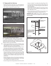
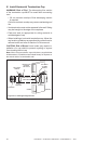
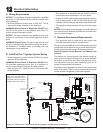
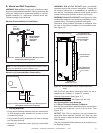
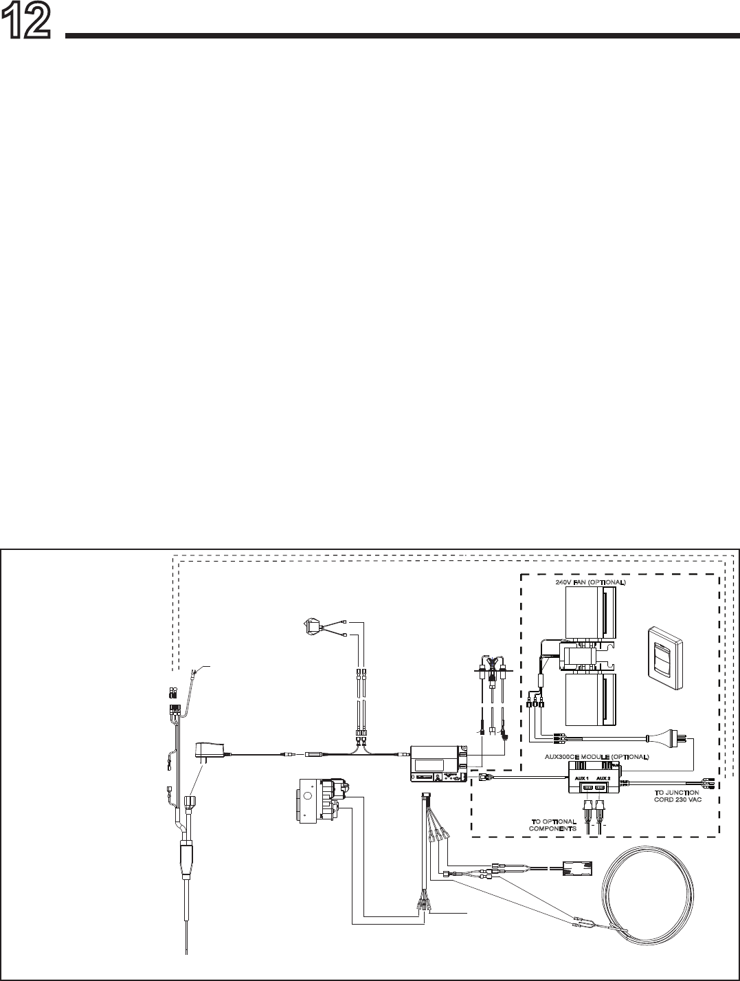
• Refer to Figure 12.1, IntelliFire Plus™ Pilot Ignition (IPI)
Wiring Diagram.
Figure12.1IntelliFirePlus™PilotIgnition(IPI)WiringDiagramwithWallSwitchorThermostat
NOTE: 1. Ignition module,
valve, pilot, and wall switch
operate on 6 volts. 230 VAC is
required at junction cord unless
equipped with battery back-up.
TO OPTIONAL
COMPONENTS
TO JUNCTION
CORD 230 VAC
AUX300CE MODULE (OPTIONAL)
240V FAN (OPTIONAL)
FAN
AUX 1
AUX 2
GROUND TO
CHASSIS
TO OPTIONAL AUX300CE
BOX AND FAN ASSEMBLY
TO CORD
ASSEMBLY 120VAC
GRAY MODULE
FLAME
SENSE
IGNITER
RC100
(OPTIONAL REMOTE
CONTROL)
ΓΕΙΩΣΗ
ORANGE
(PILOT)
GREEN
(PILOT)
BROWN-
BLACK
RED
BATTERY PACK
6V DC
THERMOSTAT WIRE
ASSEMBLY / WALL
SWITCH WIRE
WALL SWITCH
JUMPER WIRE
WIRE ASSEMBLY
MODULE RESET
SWITCH
• This appliance is equipped with an IntelliFire Plus™
control valve which operates on a 6 volt system.
• Plug the 6-volt AC power supply into the appliance junction
cord to supply power to the unit OR install four AA cell
batteries (not included) into the battery pack before use.
• This appliance ships standard with an electrical supply
cord.
NOTICE: If the supply cord is damaged, it must be replaced
by a special cord or assembly available from the manufac-
turer or its service agent.