


45Heat & Glo • XLR-N-CE, XLR-PB-CE • 2198-900 Rev. J • 5/12
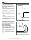
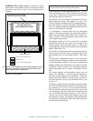
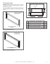
WARNING! Risk of Fire! Maintain specied air space
clearances to combustibles. Failure to comply with these
instructions may cause a re or cause the appliance to
overheat.
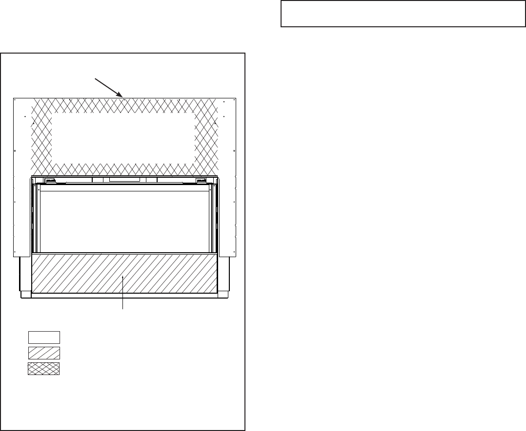
= NO SCREWS ALLOWED
= 2,5 cm MAX. SELF-TAPPING SCREWS ALLOWED
= 13 cm – 18 cm SELF-TAPPING SCREWS ALLOWED
FACTORY-INSTALLED
NON-COMBUSTIBLE BOARD
LOWER COVER PANEL
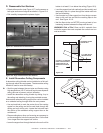
Figure13.3FinishingDetails
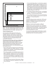
CAUTION! Risk of Glass Damage and Cuts! DO NOT
drill or install any type of screw or fastener into the lower
cover panel. Sharp screw or fastener tips may penetrate
and break the glass or cause cuts.
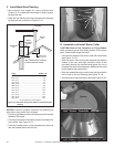
The XLR-CE must be nished using either the Tonic or
Martini decorative fronts. See Figures 13.11 and 13.12.
The nal replace installation can be accomplished by ei-
ther the Overlap Fit or Inside Fit method. Reference Sec-
tion 13.C regarding installation details associated with the
Inside Fit and Overlap Fit methods.
It is acceptable to pre-drill holes and use self-tapped
screws in the factory-installed non-combustible board to
attach non-combustible backer board for tile, marble, etc.
Refer to Figure 13.3 for acceptable screw location and
screw length requirements.
Self-tapping screws up to 2,5 cm long can be installed
through the nailing tab and outer 4,5 cm edges of the
factory-installed non-combustible board to secure the
drywall adjacent to the factory-installed non-combustible
board. See Figure 13.3.
Do not drill or install screws which may penetrate the low-
er cover panel as this will restrict required access to the
glass, battery-back-up, and remote receiver. See Figure
13.3.
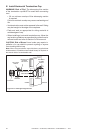
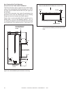
The appliance is designed to accept 1,3 cm wall sheath-
ing materials such as drywall, plywood, wood composites,
or non-combustible materials. The type of material used
depends whether the installation is an Inside or Overlap
Fit Method. Refer to Section 13.C regarding installation
details associated with the Inside an Overlap Fit meth-
ods.
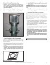
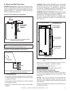
The factory-supplied non-combustible board must be
used in all installations. It must be directly attached to
structural framing adjacent to the appliance. Screw fas-
teners should be installed in the pilot holes provided in
the outer perimeter of the non-combustible board. See
Figure 13.3.
The factory-supplied board is designed such that its edg-
es will be at the approximate center of the adjacent fram-
ing, assuming it is 1-1/2 in. (3,8 cm) nominal thickness.
This will allow the wallboard joints to occur on the center
of the framing where the panels can be fastened prop-
erly. If the framing thickness is less than 1-1/2 in. (3,8 cm)
nominal, such as with formed steel systems, then it may
be necessary to adjust the adjacent framing dimensions
so that the non-combustible board and wallboard joints
are centered on the framing.
NOTE:Itisacceptabletouseahightemperature(150°C
minimumcontinuousexposuresiliconesealanttoad-
heredrywalltolowercoverpanel.
Note: Refer to Section 13.C regarding installation details as-
sociated with the Inside and Overlap Fit methods.
PILOTHOLES(11)TOATTACHNON-
COMBUSTIBLEBOARDTOFRAMING