


20
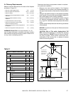
60 5/8 in.
[1540 mm]
50 in.
[1270 mm]
24 in.
[610 mm]
19 3/4 in.
[502 mm]
24 in.
[610 mm]
22 3/8 in.
[568 mm]
FLUSH
FRONT
4 in.
[102 mm]
BRICK
FRONT
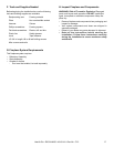
50° angle
39° angle
Grid represents
inch scale.
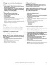
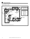
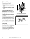
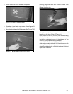
Figure 6.4 shows typical framing using combustible materials (2x4 lumber shown).
• Observe all required air space clearances to combustible materials as shown in Figure 6.1 & 6.2.
• Framing across the top of replace must be above top standoffs.
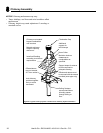
Fireplace header cannot
be positioned until after
the fireplace assembly is
in place.
Use only non-combustible
material below the top of
the front standoffs.
Framing must be
extended straight up, all
the way to the ceiling.
2 in. (51 mm)
minimum air
space clearance
to the enclosure.
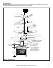
30 1/2 in.*
(772 mm)
61 5/8 in.
(1565 mm)
8 in. (203 mm) extra space
needed (both sides) for outside air
connection. If outside air duct has
no bend, this dimension may be
reduced as long as minimum
clearances are met.
* If interior of chase will be
drywalled, add the thick-
ness to this measurement.
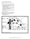
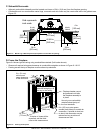
• Adjacent combustible sidewalls must be located a minimum of 24 in. (610 mm) from the replace opening.
• Combustible and non-combustible mantel legs, surrounds and stub walls may be constructed within the gridded area,
Figure 6.3.
Heat & Glo • EXCLAIM-50 • 4013-041 • Rev AA • 7/12