


29
Heat & Glo • Escape-I35-C, Escape-I30-C • 2201-901 Rev. H • 5/12
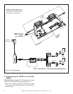
E. Optional Accessories
To connect optional accessories, the supplied cord as-
sembly should be used. See Figures 10.2 and 10.3 for
optional accessories.
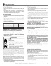
WARNING! Risk of Shock! Label all wires prior to dis-
connection when servicing controls. Wiring errors can
cause improper and dangerous operation. Verify proper
operation after servicing.
WARNING! Risk of Shock! Replace damaged wire with
type 105° C rated wire. Wire must have high temperature
insulation.
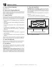
C. IPI Battery Tray/Battery Installation
The IntelliFire Plus
TM
system has a battery backup option.
Batteries should only be placed in the battery pack when
120VAC is not available. See Section 2.H.
D. Control Module Operation
See Section 2.I for control module operation instructions.
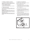
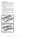
F. Installation for Fan (Optional)
On appliances already installed, removal of decorative
front surround and gas insert is required.
1. Remove appliance from wall.
2. Disconnect power by shutting off circuit breaker or
unplugging appliance power cord from its receptacle.
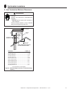
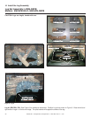
3. Remove access panel from lower rear of the fi replace
insert. See Figure 10.2.
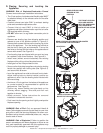
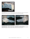
4. Secure to support base with two screws.
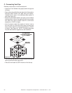
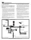
5. Connect black, white, and green wires from blower
wire assembly to each blower. See Figure 10.3.
6. Insert plug from blower cable assembly into AUX300
receptacle. See Figure 10.3.
7. Bundle and zip tie loose wires to keep them from con-
tacting blower impeller blades
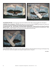
8. Position the right and left blower assembly into the rear
opening. Take care to ensure that blower housing or its
motor is clear of any adjacent metal. This will ensure
that no undue noise occurs during blower operation.
See Figure 10.3.
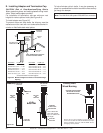
Figure 10.2
POWER CORD
FAN
ACCESS PANEL