


Heat & Glo • Escape-I35-C, Escape-I30-C • 2201-901 Rev. H • 5/12 28
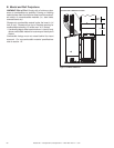
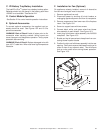
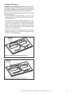
A. Wiring Requirements
NOTICE: This appliance must be electrically wired
and grounded in accordance with local codes or, in the
absence of local codes, with National Electric Code
ANSI/NFPA 70-latest edition or the Canadian Electric
Code CSA C22.1.
• This appliance comes with a 120 VAC cord assembly.
This is required for proper operation of the appliance
(Intellifi re Plus
TM
Ignition). An outlet box may be installed
in a bottom back corner of the existing solid fuel masonry
or factory built fi replace to plug in the cord assembly,
or the supplied power cord may be routed out onto the
hearth to a nearby outlet.
• A 120 VAC circuit for this product must be protected with
ground-fault circuit-interrupter protection, in compliance
with the applicable electrical codes, when it is installed in
locations such as in bathrooms or near sinks.
• Low voltage and 120 VAC voltage cannot be shared
within the same wall box.
WARNING! Risk of Shock or Explosion! DO NOT wire
120V to the valve or to the appliance wall switch. Incor-
rect wiring will damage controls.
10
10
Electrical Information
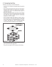
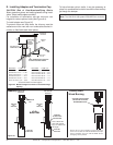
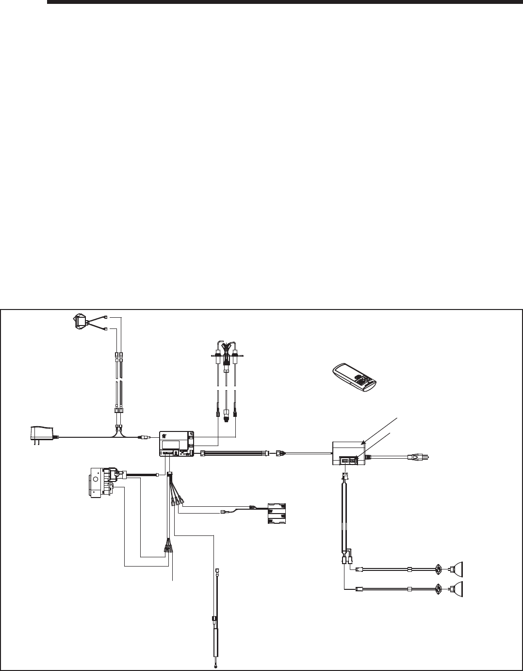
B. IntelliFire Plus
TM
Ignition System Wiring
• Wire an outlet box (120VAC) in the bottom back corner of
the existing solid fuel masonry or factory built fi replace to
plug in the cord assembly, or the supplied cord assembly
may be rerouted out onto the hearth to a nearby outlet
for proper operation of the appliance.
WARNING! Risk of Shock or Explosion! DO NOT wire
IPI controlled appliance junction box to a switched circuit.
Incorrect wiring will override IPI safety lockout.
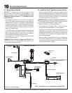
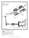
• Refer to Figure 10.1, IPI Wiring Diagram.
• This appliance is equipped with an IntelliFire Plus
TM
control valve which operates on a 6 volt system.
• Plug the 6 volt transformer plug into the appliance cord
assembly to supply power to the unit OR install 4 AA cell
batteries (not included) into the battery tray before use.
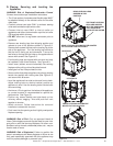
See Section 2.H for instructions on locating battery tray
and installing batteries.
• Battery longevity and performance will be affected by
the service temperatures of this appliance. Batteries
should only be used as a power source in the event of an
emergency such as an outage.
Figure 10.1 IPI Wiring Diagram
AUX WIRE EXTENSION
LIGHT WIRE ASSEMBLY
OPTIONAL
TO CORD ASSEMBLY
120VAC
AUX 300
MODULE
AUX1 AUX2
FAN
BATTERY PACK
6V DC (AA X 4)
ACCENT SOCKETS (2)
EMBER BULB 50W (2)
ORANGE
(PILOT)
GREEN
(MAIN)
TO CORD ASSEMBLY
120VAC
MODULE
ORG
WHT
INTERMITTENT PILOT IGNITOR
BLACK
RED
AUX2 NOT USED FOR INSERT MODELS.
PROTECTIVE COVER INCLUDED.
RC300 4.5V DC
(AAA X 3)
MODULE RESET
SWITCH
WIRE ASSEMBLY
NOTE: SEE FIGURE 10.3 FOR ADDITIONAL INFORMATION
EMC FILTER UNIT
BROWN
GROUND