


Heat & Glo • Paloma • 7031-220 Rev. P • 10/08 39
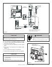
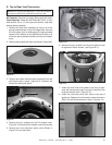
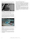
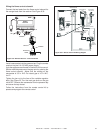
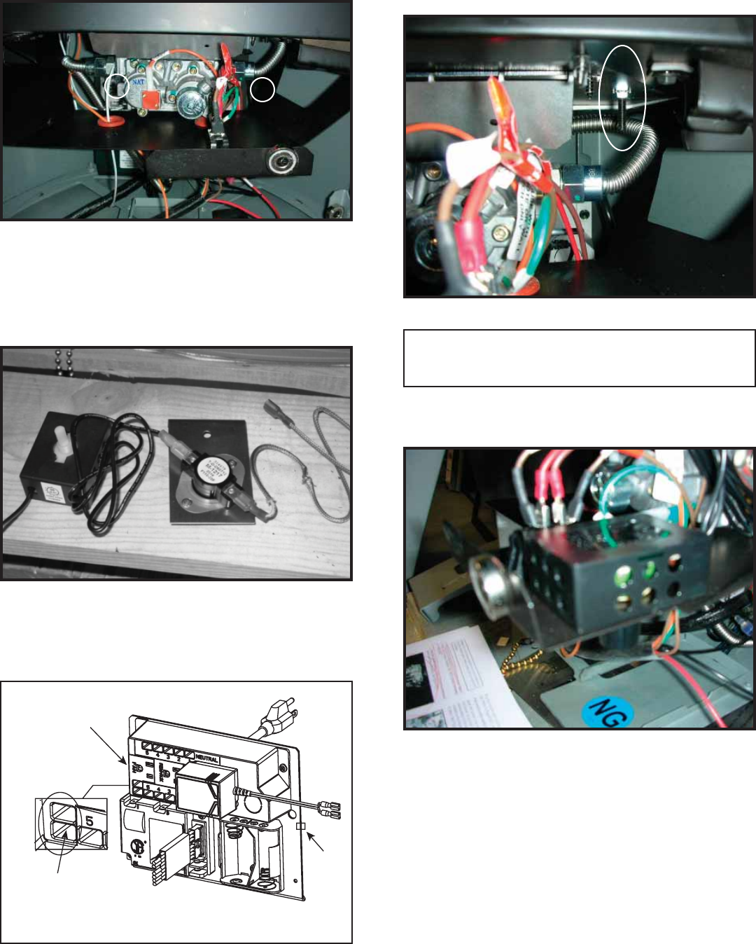
Attach enclosed wires to the temperature sensor switch/
bracket assembly. The blue wire attaches to the rear of
the bracket and one of the black wires from the variable
speed control attaches closest to the prepunched screw
hole. See Figure 8.24.
FAN OUTLET
CLIP
VARIABLE SPEED CONTROL
& TEMPERATURE SENSOR
SWITCH WIRES GO HERE
Figure 8.23
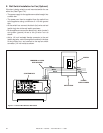
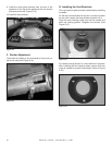
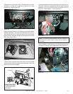
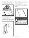
Disconnect all electrical power. Remove the front door
assembly by lifting off of appliance. Remove the lower
access door. See Figure 8.23.
Figure 8.24
Figure 8.25
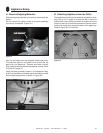
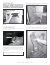
Feed the blue wire and other black wire from the variable
speed control behind the gas valve assembly. Insert the
wires into the slots indicated.
Figure 8.26
Locate the machine screw underneath the firebox on the
right side. Position the temperature sensor switch/bracket
assembly over the machine screw and attach with the
wing nut. Finger tighten. See Figure 8.26.
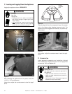
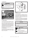
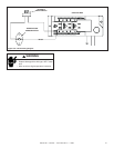
Black Wires
Black Wires
Blue Wires
Blue Wires
Figure 8.27
Attach rheostat in mating feature of control shield so that
orientation of control knob is downward. See Figure 8.27.
Note: The switch/bracket assembly must be installed so
that the sensor switch makes contact with the bottom of
the fi rebox.