


Heat & Glo • Paloma • 7031-220 Rev. P • 10/0816
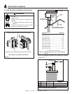
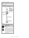
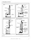
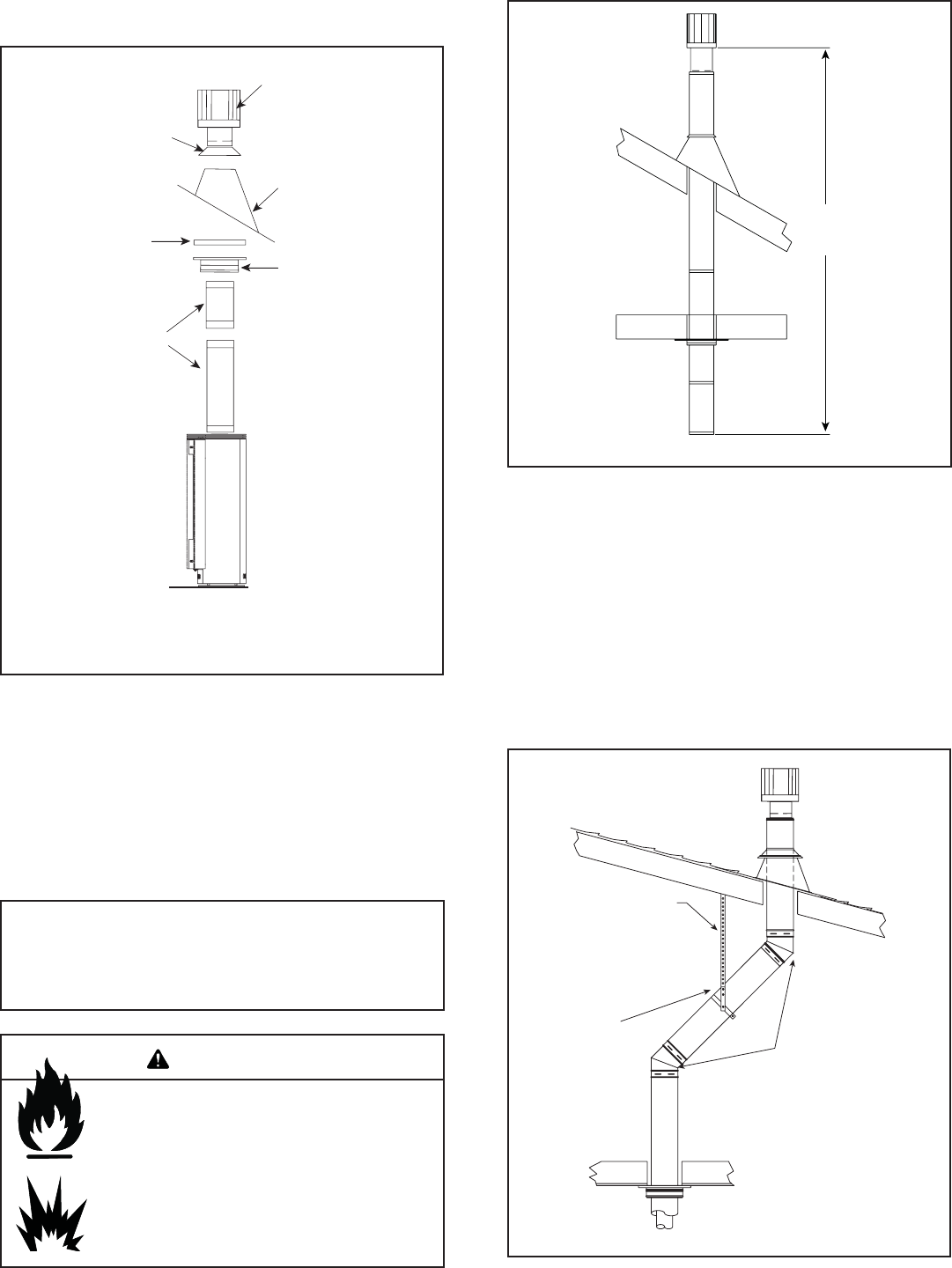
40 ft. (12 m)
MAXIMUM
Figure 5.10
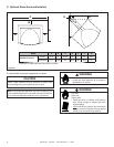
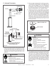
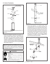
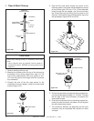
VERTICAL TERMINATION
CAP USE PART #SLK-991DA
STORM COLLAR
FLASHING
FIRESTOP
PIPE LENGTH
SUPPORT BOX
On vertical terminations use only Part #SLK-991DA or like
components. See page 55.
Figure 5.11
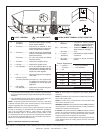
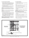
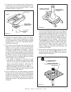
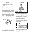
1. Check the installation instructions for required 1 in.
(25 mm) clearances (air space) to combustibles when
passing through ceilings, walls, roofs, enclosures,
attic rafters, or other nearby combustible surfaces.
See page 16, Figure 5.15. Check the instructions for
maximum vertical rise of the venting system, and any
maximum horizontal offset limitations. All offsets must
fall within the set parameters of the vent graph (Figure
5.2) located on page 12.
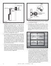
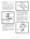
PLUMBER'S TAPE
CONNECTED TO
WALL STRAP
WALL
STRAP
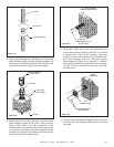
TWO 45º
ELBOWS
2. Set the gas appliance in its desired location. Drop
a plumb bob down from the ceiling to the position of
the appliance flue exit, and mark the location where
the vent will penetrate the ceiling. Drill a small hole
at this point. Next, drop a plumb bob from the roof to
the hole previously drilled in the ceiling, and mark the
spot where the vent will penetrate the roof. Determine
if ceiling joists, roof rafters, or other framing will
obstruct the venting system. You may wish to relocate
the appliance, or to offset, as shown in Figure 5.12 to
avoid cutting load bearing members.
Figure 5.12
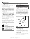
G. Vertical Termination
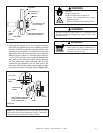
Fire Risk.
Explosion Risk.
Maintain vent clearance to combustibles as
specifi ed.
• Do not pack air space with insulation or other
materials.
Failure to keep insulation or other materials
away from vent pipe may cause fi re.
WARNING
Note: Maximum vertical rise allowable is 40 ft. (10.7 m),
Figure 5.11. Maximum number of 45º elbows permitted for a
vertical installation is eight, provided their installation does
not decrease maximum allowable horizontal run (as specifi ed
by vent graph, on page 12).