


Heat & Glo • Paloma • 7031-220 Rev. P • 10/0828
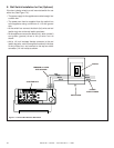
Verify the performance of the ignition system:
1. Verify pilot sparks, pilot lights, pilot stops sparking, and
the main burner turns "ON".
2. Turn the appliance "OFF". Verify that both the pilot and
burner turn "OFF".
3. Repeat Step 1 above.
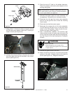
4. With the burner "ON", remove the green wire con-
nected to the valve. The main burner should shut
"OFF".
5. Reattach the green wire to the valve, and the main
burner should turn back "ON".
6. With the main burner "ON", remove the orange wire
connected to the valve. The pilot and burner should go
out, and the pilot will start to spark.
7. Turn the appliance "OFF" and reattach the orange wire
to the valve.
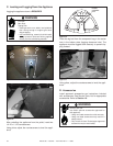
22. Light the pilot and burner and use a commercially
available, non-corrosive leak check solution to test for
leaks. Be sure to rinse off all leak check solution fol-
lowing testing and prior to placing the appliance into
operation. Extinguish the pilot and burner.
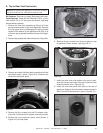
23. Reinstall the logs by following the log placement
instructions.
24. Reinstall the inner glass door assembly and the front
door assembly.
25. Turn on the appliance to check for proper burner
fl ame pattern.
26. Verify that the signed and dated conversion plate has
been added to the appliance.
Fire Risk.
Explosion Risk.
• Disconnect any electrical cords and turn
off gas supply to unit before proceeding if
converting fuel on an appliance already fully
installed.
WARNING
WARNING
Fire Risk.
Explosion Risk.
•
If the information in these instructions is
not followed exactly, a fi re, explosion or
production of carbon monoxide may result
causing property damage, personal injury or
loss of life.
• The qualifi ed service agency is responsible
for the proper installation of this conversion
kit. The installation is not proper and complete
until the operation of the converted appliance
is checked as specifi ed in the manufacturer’s
instructions supplied with the kit.
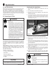
C. Gas Pressures
Proper input pressures are required for optimum appli-
ance performance. Gas line sizing requirements need to
be made following NFPA54.
Fire Risk.
Explosion Hazard.
High pressure will damage valve.
• Disconnect gas supply piping BEFORE
pressure testing gas line at test pressures
above 1/2 psig.
• Close the manual shutoff valve BEFORE
pressure testing gas line at test pressures
equal to or less than 1/2 psig.
Verify inlet pressures.
• High pressure may cause overfi re condition.
• Low pressure may cause explosion.
• Verify minimum pressures when other
household gas appliances are operating.
Install regulator upstream of valve if line
pressure is greater than 1/2 psig.
Pressure requirements for appliance are shown in the
table below. Minimum pressures must be met when other
household gas appliances are operating.
WARNING
WARNING
Pressure Natural Gas Propane
Minimum inlet pressure
5.0 inches
w.c.
11.0 inches
w.c.
Maximum inlet gas pressure
7.0 inches
w.c.
14.0 inches
w.c.
Manifold pressure
3.5 inches
w.c.
10.0 inches
w.c.
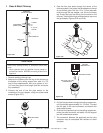
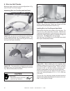
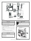
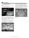
21. Place one piece grommet over pilot wires and supply
tube. Slide and snap into mating rectangular slot.
Make sure it fi ts securely. See Figure 6.6.
Figure 6.6